Method and arrangement for low or non-rotating artillery shells

a technology of low or non-rotating artillery shells and methods, applied in the direction of weapons, projectiles, ammunition projectiles, etc., can solve the problem of not being able to provide this type of missile with a well-functioning guidance system

Inactive Publication Date: 2007-04-19
BAE SYST BOFORS
View PDF16 Cites 13 Cited by
  • Summary
  • Abstract
  • Description
  • Claims
  • Application Information

AI Technical Summary

Benefits of technology

[0008] A way of solving this problem which has already been tested to an at least limited extent is to let the part of the missile in which the fins are secured constitute a unit which can rotate freely in relation to the rest of the missile about an axis concentric with the longitudinal axis of the missile. In this way, the effect of the control moment on the fins cannot be transferred to the front part of the missile, as a result of which the missile is made easier to control.

Problems solved by technology

However, the high rotational velocity has at least hitherto made it impossible to provide this type of missile with a well-functioning guidance system.

Method used


Image

  • Method and arrangement for low or non-rotating artillery shells
  • Method and arrangement for low or non-rotating artillery shells
  • Method and arrangement for low or non-rotating artillery shells

Examples


Embodiment Construction

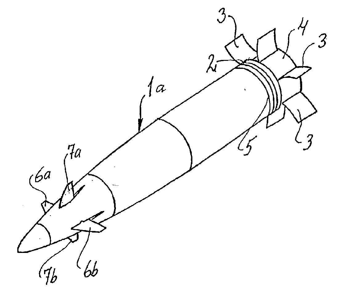
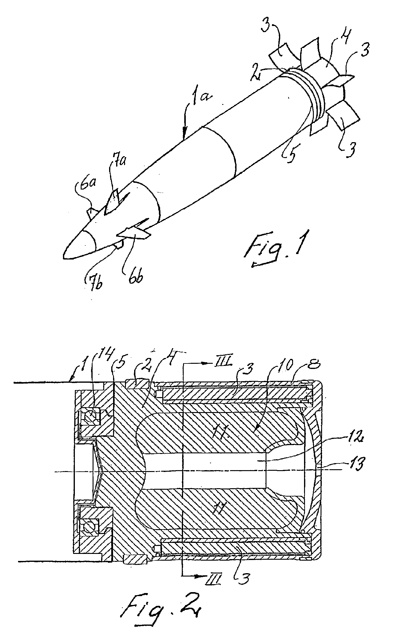
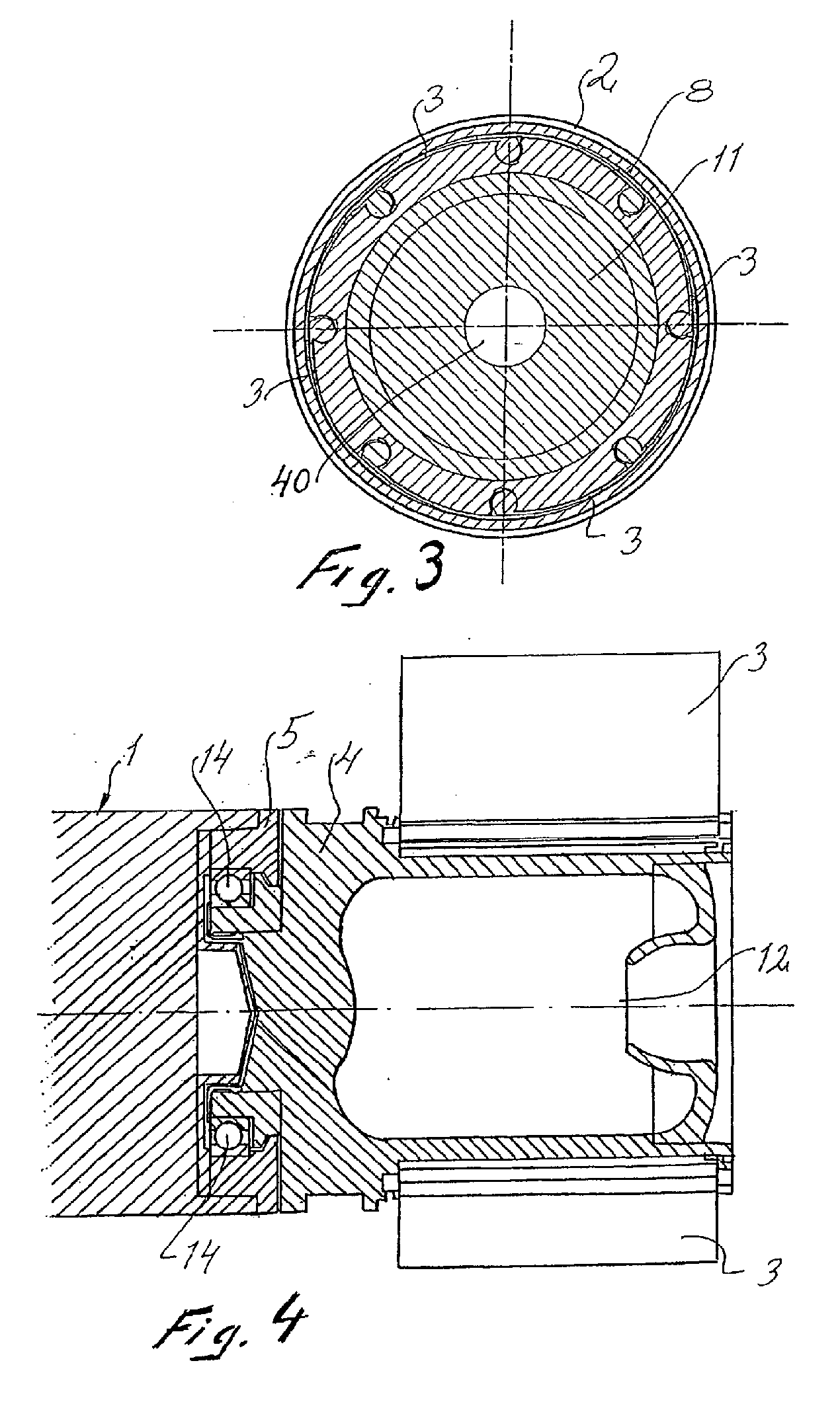
[0028] The missile shown in FIG. 1, in this case the shell 1a, is provided with a band track 2 for a drive band which is conventionally known as a “skidding drive band”, which is generally lost when the shell leaves the barrel in order to effect low inherent rotation or no rotation of the shell. A number of deployable fins 3 are shown fully deployed in the figure and which are fixed on a body part 4 which rotates freely relative to the rest of the shell about an axis concentric with the longitudinal axis of the shell. The dividing plane between the shell 1 and the body part 4 has been labeled 5. In addition, the shell 1 has two pairs of controllable canard fins 6a, 6b and 7a, 7b arranged on a respective quadrant axis and with which the course and trajectory of the shell can be corrected in accordance with control commands received either from an internal target seeker or from the launch site, via satellite, radar or other means. The way in which the shell receives control commands h...


PUM


Abstract

This disclosure relates to a method and an arrangement for low or non-rotating artillery shells fired from launch weaponry, and which introduces a portion of the barrel pressure built up in the barrel during the launch phase into a chamber arranged in the low or non-rotating artillery shell which is delimited in at least one direction by an element which is movable relative to the rest of the shell when a differential pressure between the chamber and the external environment of the shell is sufficient to move the element. The moveable element may be a protective casing covering fins of the artillery shell.

Description

CROSS REFERENCE TO RELATED APPLICATIONS [0001] This application is a continuation of co-pending application Ser. No. 10 / 312,763 filed on Jul. 1, 2003. Application Ser. No. 10 / 312,763 is a National Stage Entry of International Application PCT / SE01 / 01331, filed on Jun. 13, 2001. International Application PCT / SE01 / 01331 claims priority to Swedish application serial number 00024794.4, filed on Jul. 3, 2000. The entire contents of each of these applications are incorporated herein by reference.BACKGROUND [0002] The present disclosure relates to a method and an arrangement for producing a relative displacement of specific elements included in artillery missiles, this relative displacement being intended to be activated as soon as the missile has left the barrel from which it has been fired. [0003] The disclosure is in the first instance intended to be used in those artillery missiles which are fired without rotation or at a low inherent rotation about their longitudinal axis (e.g., by use...

Claims


Application Information

Patent Timeline
Patent Type & Authority Applications(United States)
IPC IPC(8): F42B10/00F42B10/16F42B10/18F42B10/20F42B10/40
CPCF42B10/16F42B10/40F42B10/20F42B10/18
Inventor JOHNSSON, STIGHELLMAN, ULFHOLMQVIST, ULF
Owner BAE SYST BOFORS
Why Eureka
Try Eureka