System and method for correlating captured images with their site locations on maps

a captured image and site location technology, applied in the field of system and method for correlating captured images with their site locations on maps, can solve the problems of difficult accurate determination of the “capture zone” of image data, limited practical application, and inability to readily obtain operative image systems and methods, etc., to achieve accurate representation

Inactive Publication Date: 2007-03-29
PATTERSON RAUL DARIO
View PDF12 Cites 30 Cited by
  • Summary
  • Abstract
  • Description
  • Claims
  • Application Information

AI Technical Summary

Benefits of technology

[0012] In the one or more preferred embodiments described herein, the position determining capabilities of the digital camera comprises a geographic positioning system such as the well known Global Positioning System (GPS). Having such capabilities, the imaging assembly can be disposed at any appropriate location relative to the subject matter of the captured image data. Operation of the GPS, or other position determining facility, will enhance the precise determination of the position of the imaging assembly when it is properly positioned to capture the image of the predetermined subject matter.
[0019] The display assembly may be directly associated with the aforementioned processor / hardware or may be peripherally connected to or otherwise associated therewith. In any case, the accessible display data would either be downloaded directly into the processor or made available by virtue of a variety of other storage media such as optical storage disk i.e. DVD, etc. Once viewed, the accessible display data will include the aforementioned appropriate map application populated with at least one but perhaps more practically a plurality of shapes and / or markings representing capture zones and / or a plurality of oriented symbols representing camera positions / orientations, respectively. The one or more capture zone figures and / or indicia symbols would be accurately disposed on the map application and be linked to the integrated image data comprised of the photographic or video imaging.
[0024] Interactive accessing of the DVD containing the display data would result in a visual display of appropriate map software or applications representative of the theme or entertainment park. Populated thereon would be a plurality of symbols each representative of the location of the imaging assembly during capture of the various images. Accessing the symbols by a pointer or the like would result in a visual display of the photograph or video of the subject matter along with the surrounding environment where appropriate. Also the one or more displayed capture zones associated with each of the one or more captured images would thereby provide an accurate representation on the displayed map application of the subject matter of the captured images.

Problems solved by technology

However, one drawback of previously proposed geographic organizational displays of digital image data is the generally recognized difficulty of accurately determining the “capture zone” of image data as it relates to other elements present in a map display.
Difficulties arise, at least in part, because operative image systems and methods are not readily available and accordingly not widely used.
However, the practical application is limiting to the extent that although certain physical parameters of the camera may be shown on the map display, such as position and orientation, an accurately defined capture zone is not.
As such, the objects and the surroundings that have been photographed cannot be accurately determined on a map.

Method used


Image

  • System and method for correlating captured images with their site locations on maps
  • System and method for correlating captured images with their site locations on maps
  • System and method for correlating captured images with their site locations on maps

Examples


Embodiment Construction

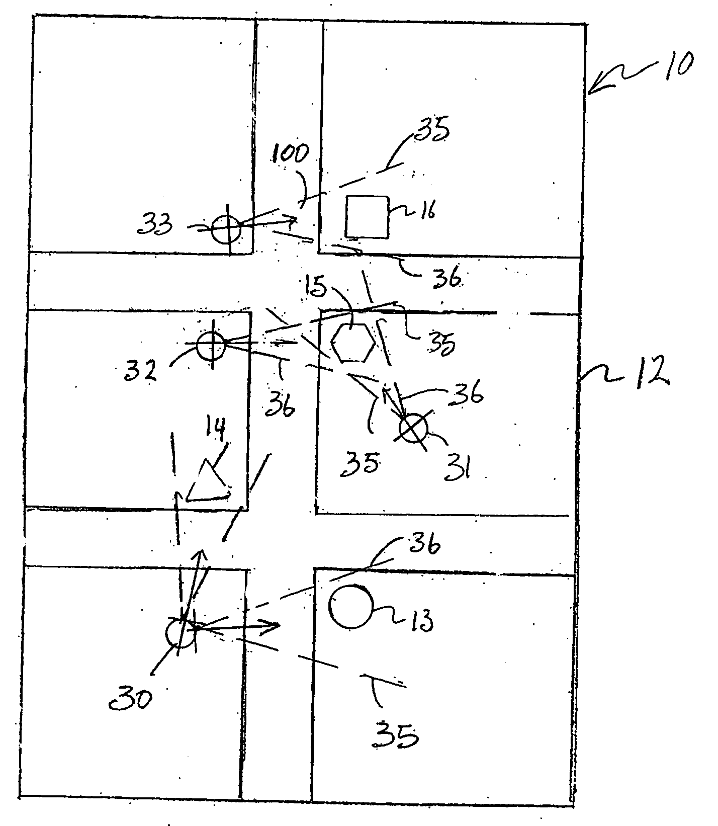
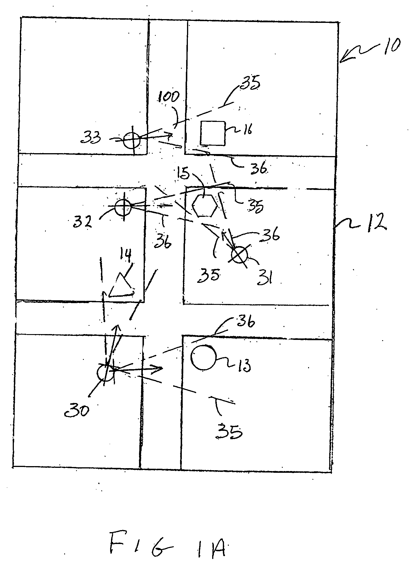
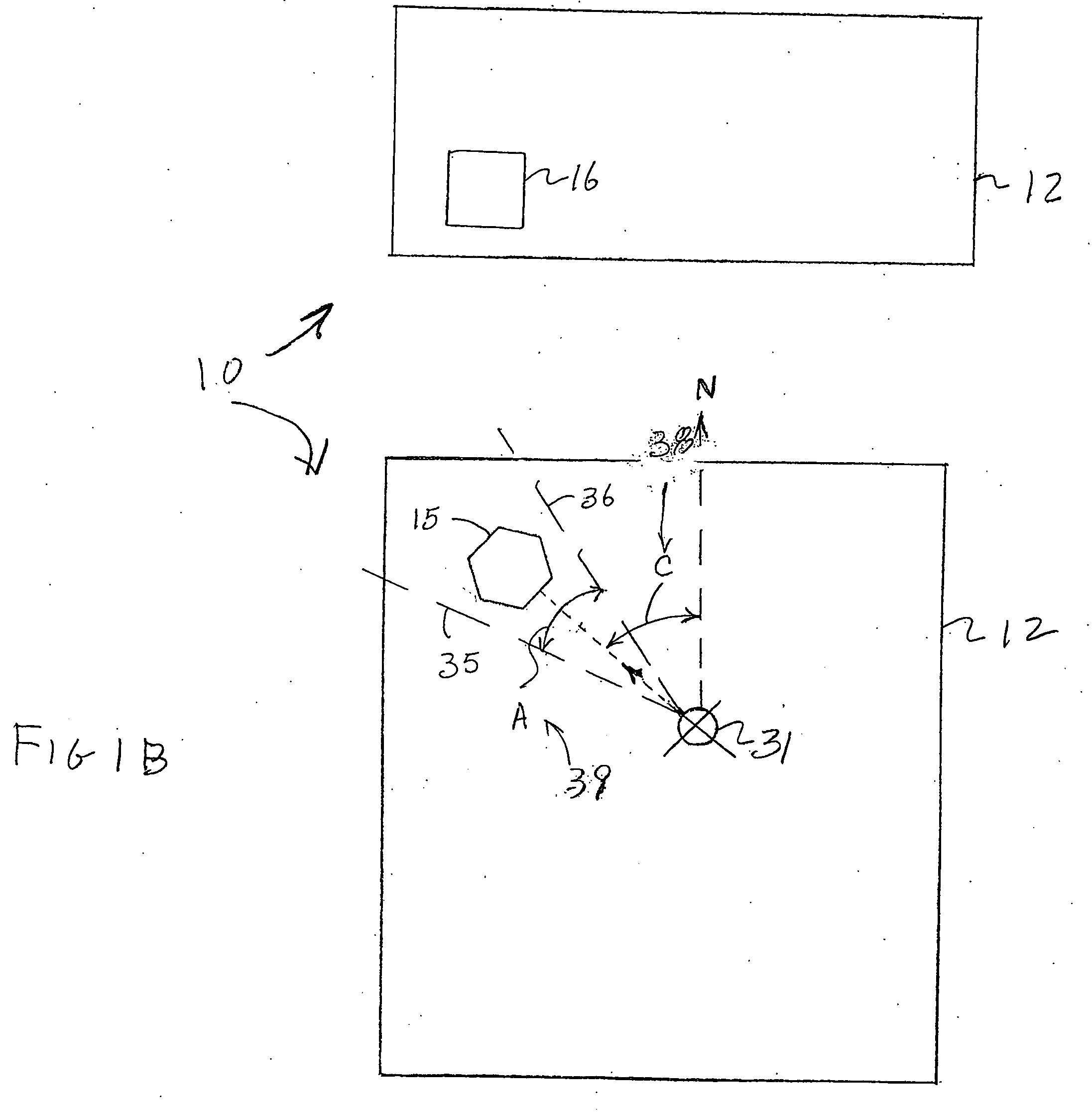
[0035] The present invention is directed to a system and method for correlating captured images with various site locations associated with the position of the subject matter of the captured images, as well as a digital imaging assembly by which the images are captured. As should be apparent, the imaging assembly may be structured to capture still images or video. With reference to the accompanying Figures, the structural and operative features including hardware and software applications associated with the various preferred embodiments of the subject invention are schematically represented.

[0036] Accordingly, FIGS. 1A and 1B are representative of mapping data generally indicated as 10 and more specifically represented in the form of a predetermined map application 12 on which at least one, but more practically, a plurality of different objects 13, 14, 15, 16, etc. are represented in their appropriate geographical location. More specifically, the map application 12 is a software a...


PUM


Abstract

A system and method for spatial representation of image capture zones associated with captured images, their site locations and imaging assemblies, which capture the intended image, on a corresponding map of the site location of an imaging assembly and the subjects of the captured images display. The imaging assembly includes location, orientation position and orientation determining capabilities, wherein metadata associated with the location, and orientation of the imaging assembly during capturing of the image is associated with the original photographic image data to create the capture zones on a map display. The map display includes a population of one or more capture zones each indicative of a position and orientation of the imaging assembly when an image was captured and field of view of the imaging assembly. When the capture zones are accessed, a representation of the captured photographic image data is displayed.

Description

BACKGROUND OF THE INVENTION [0001] 1. Field of the Invention [0002] This invention relates to a system and method of correlating captured images with site locations associated with the position of both the subject matter of the captured image and an imaging assembly used to photograph the subject matter. The imaging assembly is operatively associated with position, orientation and angle of view determining capabilities such that the field of view, angle of orientation and other data can be represented on a map application populated with symbols indicative of capture zones of the image data. [0003] 2. Description of the Related Art [0004] With the fairly recent advancement in modern technology relating to digital photography, including the capturing of both still and moving images, the captured image data can be appropriately processed for versatile and interactive display. Further, the existence of positioning systems such as the popular Global Positioning System (GPS) enables extre...

Claims


Application Information

Patent Timeline
Patent Type & Authority Applications(United States)
IPC IPC(8): H04N5/222
CPCG09B29/10H04N2201/3277H04N2201/3253H04N1/32128
Inventor PATTERSON, RAUL DARIO
Owner PATTERSON RAUL DARIO
Why Eureka
Try Eureka