
Vacuum cleaner with dirt collection vessel having a stepped sidewall

a vacuum cleaner and dirt collection technology, which is applied in the direction of vacuum cleaners, cleaning filter means, domestic applications, etc., can solve the problems of affecting the cleaning efficiency of vacuum cleaners, and entrapping dirt and debris in airstreams

Inactive Publication Date: 2007-03-29
PANASONIC OF NORTH AMERICA
View PDF25 Cites 172 Cited by
  • Summary
  • Abstract
  • Description
  • Claims
  • Application Information

AI Technical Summary

Benefits of technology

[0007] In accordance with the purposes of the present invention as described herein, an improved vacuum cleaner is provided. That vacuum cleaner includes a nozzle assembly with a suction inlet and a canister assembly. A suction generator is carried on one of the canister assembly and nozzle assembly. Similarly, a dirt collection vessel is carried on one of the canister assembly and the nozzle assembly. The dirt col

Problems solved by technology

At times, however, some dirt and debris remains entrapped within the airstream.
However, larger debris is sometimes drawn toward and closes some of the airstream apertures provided in the prefilter.
In such a circumstance, the cleaning efficiency of the vacuum cleaner becomes impaired.

Method used


Image

  • Vacuum cleaner with dirt collection vessel having a stepped sidewall
  • Vacuum cleaner with dirt collection vessel having a stepped sidewall
  • Vacuum cleaner with dirt collection vessel having a stepped sidewall

Examples


Embodiment Construction

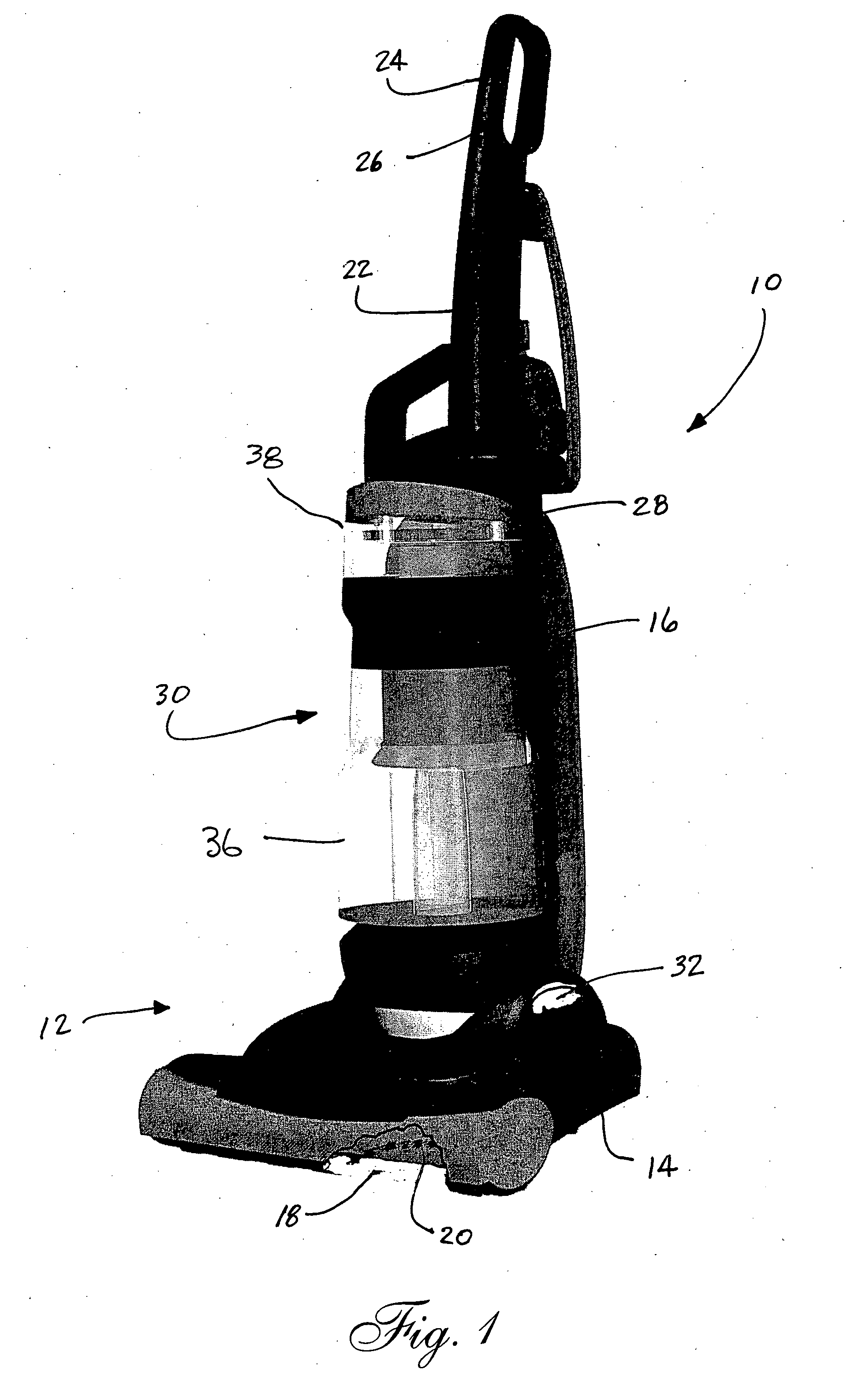
[0025] Reference is now made to FIG. 1 which illustrates the floor cleaning apparatus 10 of the present invention. In the illustrated embodiment, the floor cleaning apparatus 10 comprises an upright vacuum cleaner. It should be appreciated, however, that the apparatus 10 may just as easily be a canister vacuum cleaner or a handheld vacuum cleaner.

[0026] As illustrated, the apparatus 10 includes a housing 12 including both a nozzle assembly 14 and a canister assembly 16. The nozzle assembly 14 includes a suction inlet 18 through which air entrained with dirt and debris is drawn into the vacuum cleaner. A rotary agitator 20 is mounted to the nozzle assembly 14 and extends across the suction inlet 18.

[0027] The canister assembly 16 includes a handle 22 having a handgrip 24. An actuator switch 26 for turning the vacuum cleaner on and off is provided adjacent the handgrip. In addition the canister assembly 16 includes a cavity or receiver 28 for receiving and holding a dirt collection ...


PUM


Abstract

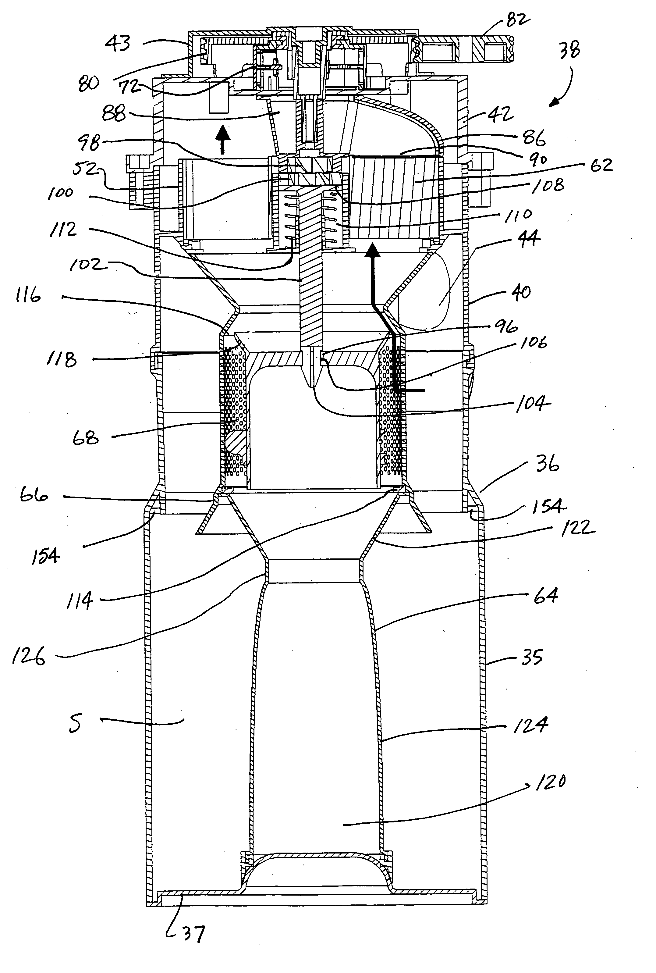
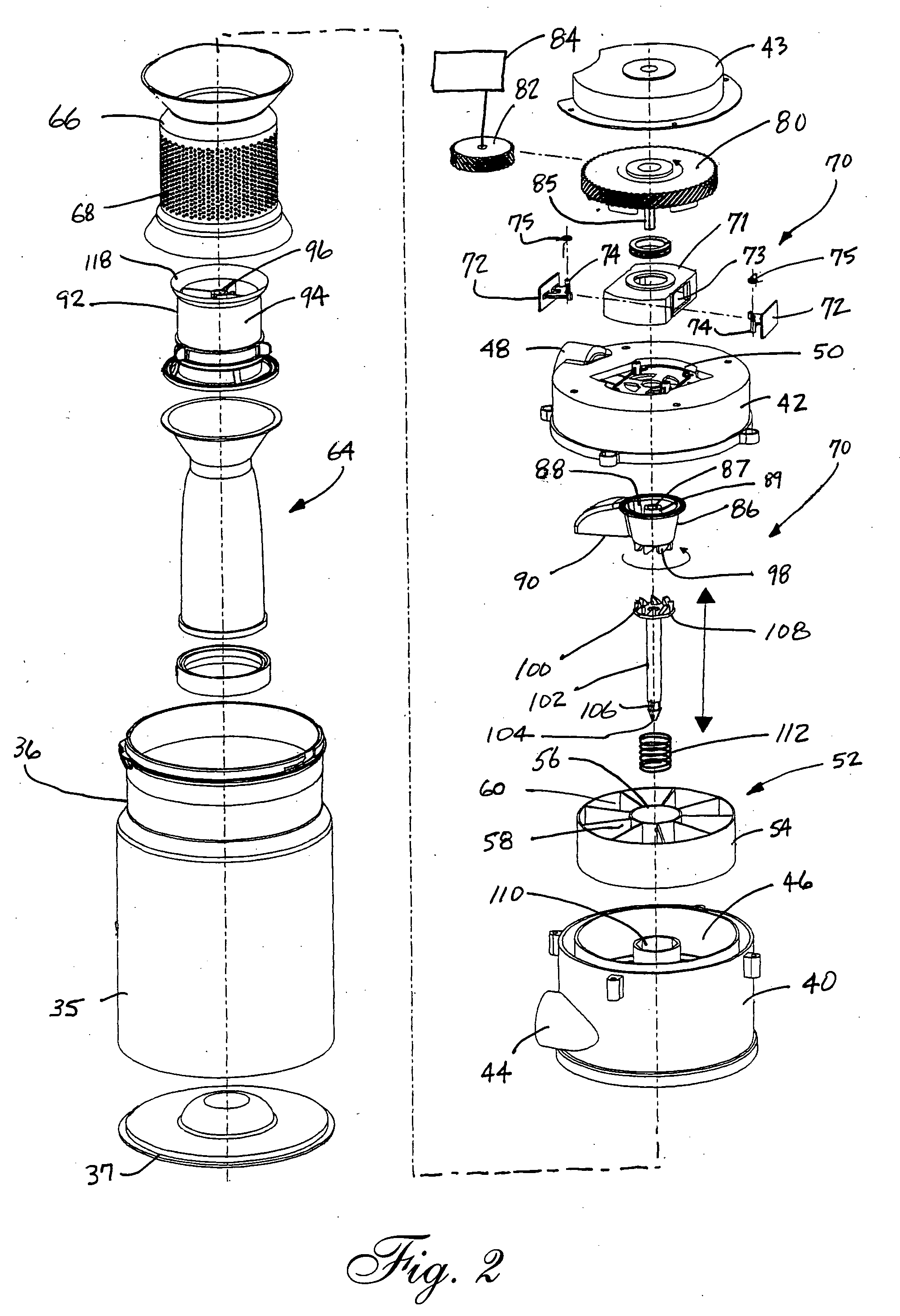
A vacuum cleaner is provided including a nozzle assembly with a suction inlet and a canister assembly. A suction generator and dirt collection vessel ate carried on one of the nozzle assembly and canister assembly. The dirt collection vessel includes a base wall, a stepped sidewall and a dirt collection chamber. The stepped sidewall has a first cylindrical section with a circumference C1, and a second cylindrical section with a circumference C2 where C1, C1>C2. In addition the stepped sidewall includes a step connecting the first and second cylindrical sections where the step and first cylindrical section define an included angle A1≦90°.

Description

TECHNICAL FIELD [0001] The present invention relates generally to the floor care equipment field and, more particularly, to a vacuum cleaner equipped with a dirt collection vessel having a stepped sidewall providing enhanced cleaning efficiency. BACKGROUND OF THE INVENTION [0002] A vacuum cleaner is an electromechanical appliance utilized to effect the dry removal of dust, dirt and other small debris from carpets, rugs, fabrics or other surfaces in domestic, commercial and industrial environments. In order to achieve the desired dirt and dust removal, most vacuum cleaners incorporate a rotary agitator. The rotary agitator is provided to beat dirt and debris from the nap of the carpet or rug while a pressure drop or vacuum is used to force air entrained with this dirt and debris into the nozzle of the vacuum cleaner. The particulate laden air is then drawn into a dirt collection vessel. The air is then drawn through a filter before being directed through the motor of the suction gene...

Claims


Application Information

Patent Timeline
IPC IPC(8): A47L9/16
CPCA47L9/122A47L9/1608A47L9/20A47L9/1683A47L9/1666
Inventor KITAMURA, HIDENORIPROFFITT, DONALD E.
Owner PANASONIC OF NORTH AMERICA
Learn More