
Clamping system and clamping method

a technology of clamping system and clamping method, which is applied in the direction of manufacturing tools,foundry moulding apparatus, food shaping, etc., can solve the problems of degrading the degree of parallelism between die plates, dimensional errors of products become larger, and easy burrs

Inactive Publication Date: 2007-03-01
TOSHIBA MASCH CO LTD
View PDF5 Cites 13 Cited by
  • Summary
  • Abstract
  • Description
  • Claims
  • Application Information

AI Technical Summary

Benefits of technology

[0006] An object of the present invention is to provide a clamping system and a clamping method able to suppress the degradation of the degree of parallelism during the period after die contact to the completion of clamping and able to maintain the degree of parallelism between die plates at the time of the completion of the clamping.
[0012] According to the present invention, therefore, the degradation of the degree of parallelism during the period from die contact to the completion of clamping is suppressed, and the degree of parallelism between die plates can be maintained at the time of the completion of clamping.

Problems solved by technology

In a clamping system, where the degree of parallelism between a movable die plate and a fixed die plate cannot be held, the dimensional error of the product becomes larger, burrs easily occur, and other problems arise.
In the clamping system, however, sometimes the degree of parallelism between die plates is degraded even during the period after the die contact to the completion of clamping.

Method used


Image

  • Clamping system and clamping method
  • Clamping system and clamping method
  • Clamping system and clamping method

Examples


Embodiment Construction

[0020] Preferred embodiments of the present invention will be described in detail below while referring to the attached figures.

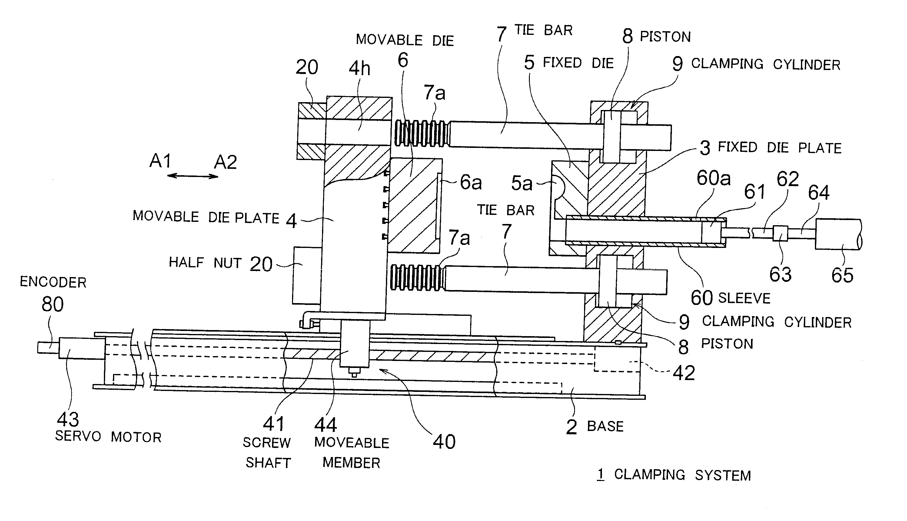
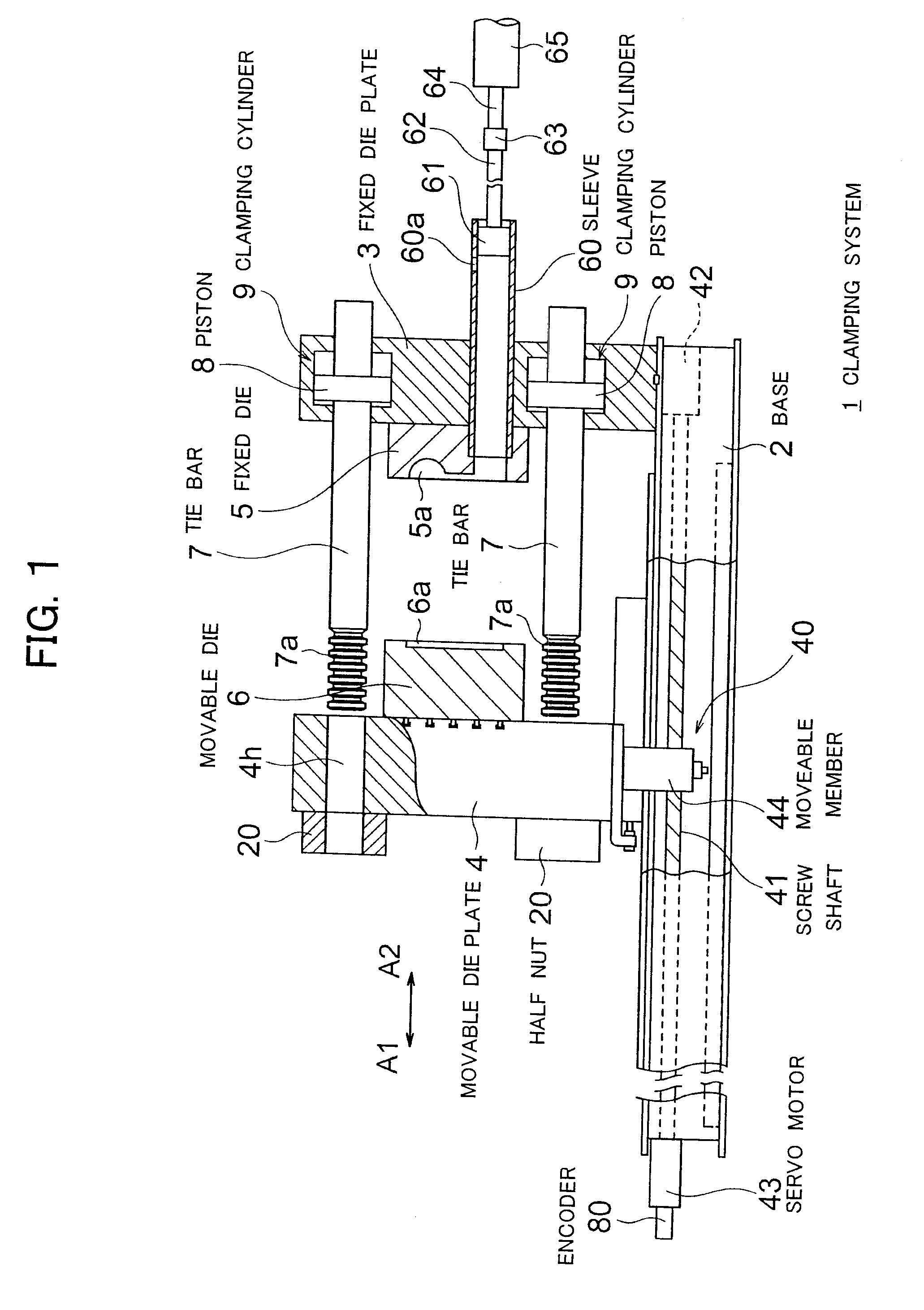
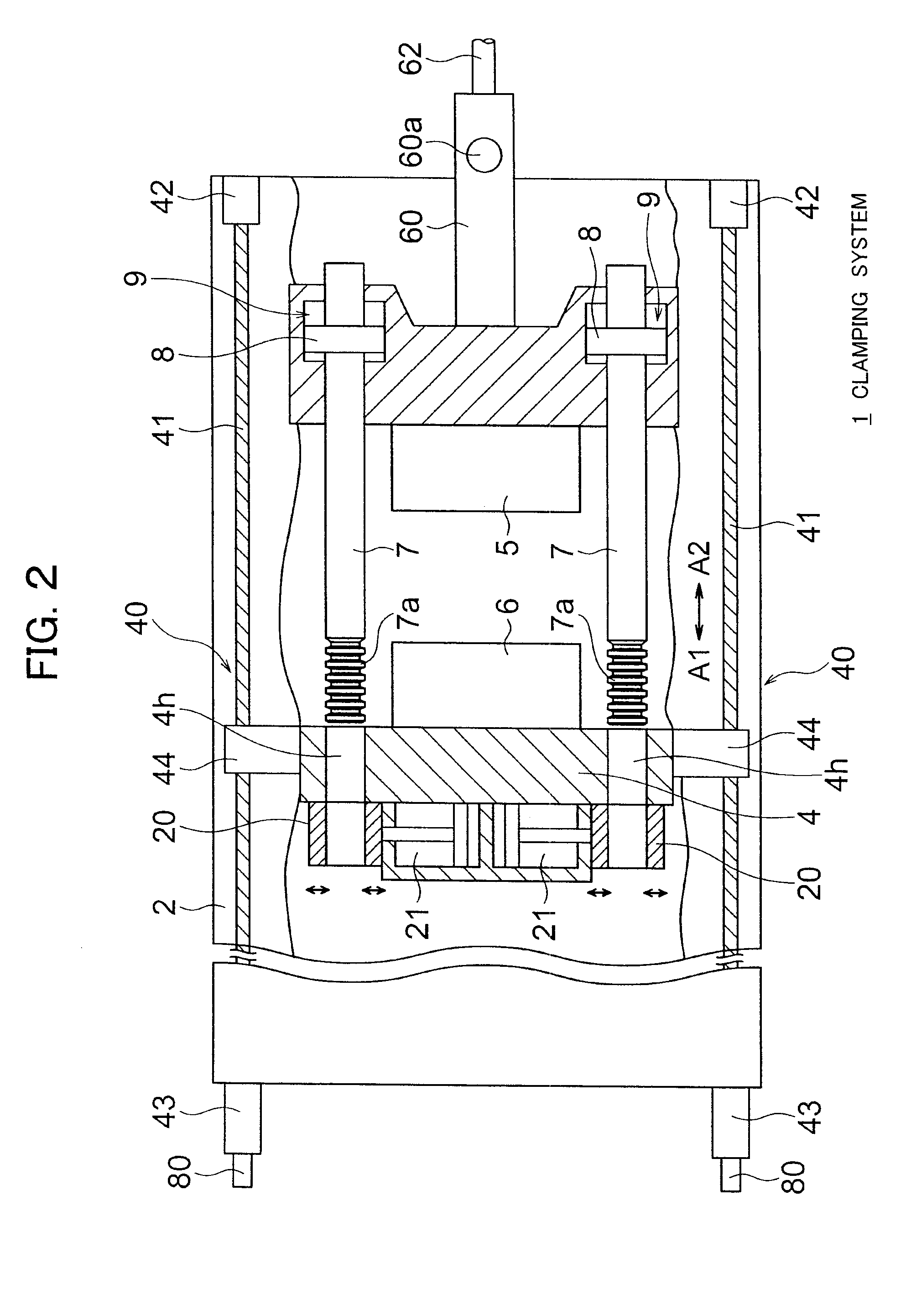
[0021]FIG. 1 is a front view including a sectional view of a part showing the configuration of a machine part of a clamping system 1 according to an embodiment of the present invention and shows a state before the adjustment of the die thickness. Further, FIG. 2 is a view of the clamping system 1 of FIG. 1 as seen from above. FIG. 3 is a front view including a sectional view of a part showing the configuration of the machine part of the clamping system 1 and shows a state where molten metal ML is injected after the completion of clamping. Note that, the clamping system according to the present embodiment is applied to a die cast machine. The clamping system 1 is constituted as a so-called composite type clamping system having a movement mechanism 40 mainly utilized for opening and closing the dies and clamping cylinders 9 mainly utilized for the clamping. ...


PUM

PropertyMeasurementUnit
clamping forceaaaaaaaaaa
movement speedaaaaaaaaaa
speedaaaaaaaaaa

Abstract

A clamping system provided with a fixed die plate, a movable die plate, a plurality of tie bars, half nuts able to be coupled with or release coupled parts of a plurality of tie bars, clamping cylinders accommodating pistons of a plurality of tie bars, position sensors detecting positions of pistons, a plurality of direction control valves connected to a plurality of clamping cylinders, and a control unit controlling the plurality of direction control valves so that a difference of movement amounts of pistons among the plurality of tie bars from the time of die contact to the time of the completion of clamping becomes within a predetermined permissible value based on detection results of the position sensors.

Description

BACKGROUND OF THE INVENTION [0001] 1. Field of the Invention [0002] The present invention relates to a clamping system and a clamping method. [0003] 2. Description of the Related Art [0004] In a clamping system, where the degree of parallelism between a movable die plate and a fixed die plate cannot be held, the dimensional error of the product becomes larger, burrs easily occur, and other problems arise. Therefore various techniques for keeping the degree of parallelism between a movable die plate and a fixed die plate have been proposed. For example, Japanese Patent Publication (A) No. 2004-322609 discloses a technique of providing a plurality of ball screws for moving the movable die plate in a die opening and closing direction on the peripheries of the movable die plate and the fixed die plate along the tie bars and individually controlling the drive operations of these plurality of ball screws so as to perform the clamping while maintaining the degree of parallelism between the...

Claims


Application Information

Patent Timeline
Patent Type & Authority Applications(United States)
IPC IPC(8): B29C45/64B29C45/76
CPCB22D17/266B29C45/6728B29C45/7653B29C2045/1788B29C2945/7611B29C2945/76224B29C2945/76869B29C2945/76387B29C2945/76391B29C2945/76568B29C2945/76702B29C2945/76866B29C2945/76234
Inventor TSUJI, MAKOTONODA, SABURO
Owner TOSHIBA MASCH CO LTD
Learn More