
Failure determination system and method for temperature sensors, as well as engine control unit

Inactive Publication Date: 2007-03-01
HONDA MOTOR CO LTD
View PDF6 Cites 47 Cited by
  • Summary
  • Abstract
  • Description
  • Claims
  • Application Information

AI Technical Summary

Benefits of technology

[0015] With the configuration of this failure determination method, it is possible to obtain the same advantageous effects as provided by the failure determination system according to the first aspect of the present invention.
[0016] To attain the above object, in a fourth aspect of the present invention, there is provided a method of determining failures of a plurality of temperature sensors provided in an internal combustion engine, comprising a stoppage detecting step of detecting whether or not the engine has stopped, an initial temperature-storing step of storing respective temperatures detected by the temperature sensors when stoppage of the engine is detected, as initial temperatures, a dimensionless value-calculating step of making dimensionless the respective temperatures detected by the temperature sensors after stoppage of the engine based on the corresponding initial temperatures, to thereby calculate respective dimensionless values of the temperatures detected by the temperature sensors, and a failure determination step of determining failures of the temperature sensors based on results of comparisons between the calculated dimensionless values of the temperatures detected by the temperature sensors.
[0017] With the configuration of this failure determination method, it is possible to obtain the same advantageous effects as provided by the failure determination system according to the second aspect of the present invention.
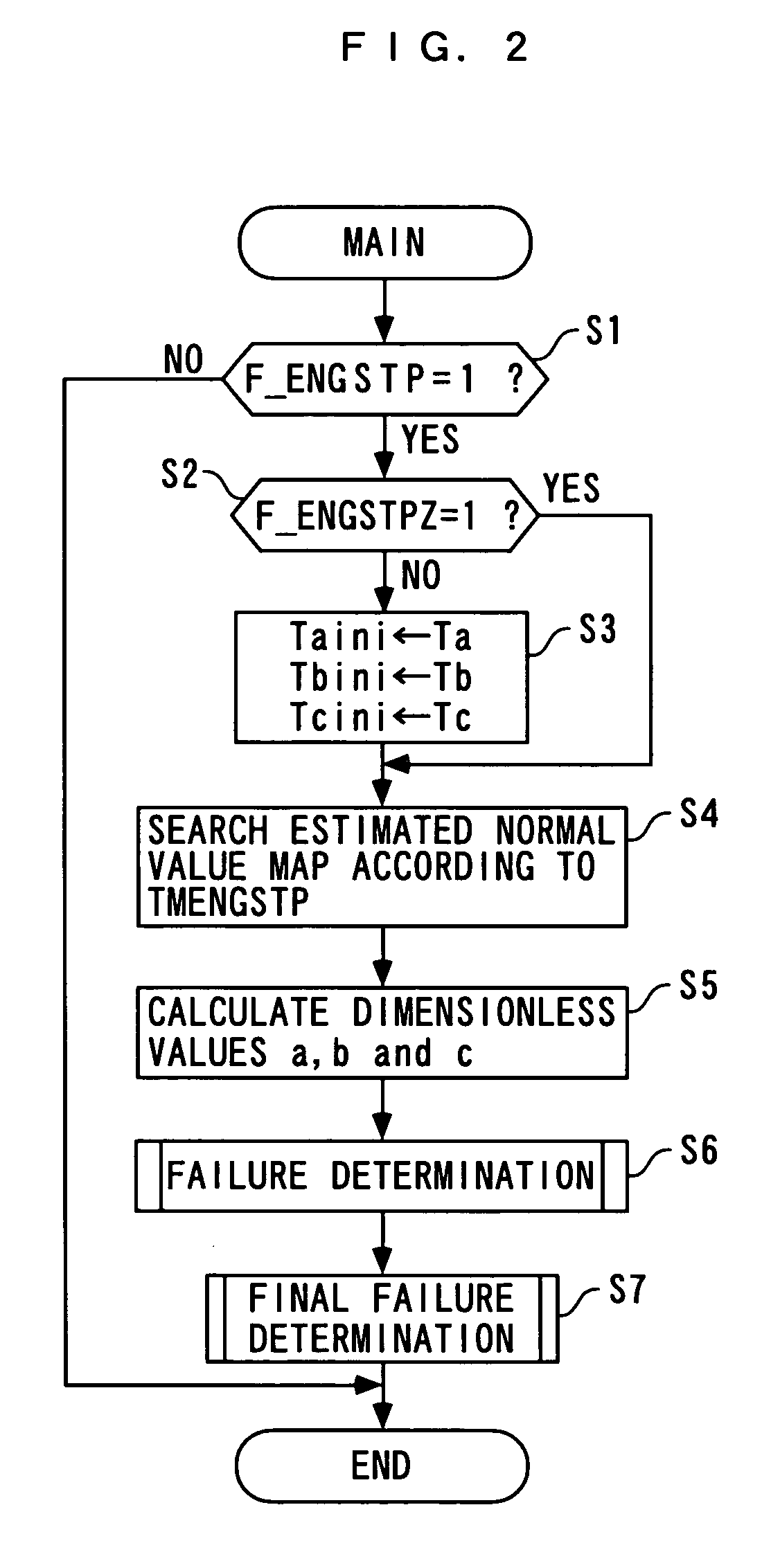
[0018] To attain the above object, in a fifth aspect of the present invention, there is provided an engine control unit including a control program for causing a computer to determine failures of a plurality of temperature sensors provided in an internal combustion engine, wherein the control program causes the computer to detect whether or not the engine has stopped, store respective temperatures detected by the temperature sensors when stoppage of the engine is detected, as initial temperatures, make dimensionless the respective temperatures detected by the temperature sensors after stoppage of the engine based on the corresponding initial temperatures, to thereby calculate respective dimensionless values of the temperatures detected by the temperature sensors, set in advance an estimated value of a dimensionless value of a temperature to be detected when the temperature sensors are normal, as an estimated normal value, and determine failures of the temperature sensors based on results of comparisons of the respective calculated dimensionless values of the temperatures detected by the temperature sensors with the set estimated normal value.
[0019] With the configuration of this engine control unit, it is possible to obtain the same advantageous effects as provided by the failure determination system according to the first aspect of the present invention.
[0020] To attain the above object, in a sixth aspect of the present invention, there is provided an engine control unit including a control program for causing a computer to determine failures of a plurality of temperature sensors provided in an internal combustion engine, wherein the control program causes the computer to detect whether or not the engine has stopped, store respective temperatures detected by the temperature sensors when stoppage of the engine is detected, as initial temperatures, make dimensionless the respective temperatures detected by the temperature sensors after stoppage of the engine based on the corresponding initial temperatures, to thereby calculate respective dimensionless values of the temperatures detected by the temperature sensors, and determine failures of the temperature sensors based on results of comparisons between the calculated dimensionless values of the temperatures detected by the temperature sensors.

Problems solved by technology

Therefore, the accuracy of the estimated convergence values is not necessarily high, which sometimes prevents accurate failure determination of the temperature sensors.
In this case, however, it takes a long time to determine failures of the temperature sensors.
In such a case, even if convergence values obtained from the respective temperature sensors are compared with each other, it is impossible to carry out proper failure determination of the temperature sensors in actual operating temperature ranges thereof.
For example, in general, exhaust gas temperature sensors for detecting the temperature of exhaust gases are not configured to be capable of ensuring sufficiently high detection accuracy in a normal temperature range, including outside air temperature, since they are used in a very high temperature range of which values are 300 to 400° C. even immediately after stoppage of the engine.
Therefore, it is impossible to properly determine failures of the two temperature sensors in the operating temperature range by comparison between the convergence values which are obtained from the respective temperature sensors but are largely different from the operating temperature range.

Method used


Image

  • Failure determination system and method for temperature sensors, as well as engine control unit
  • Failure determination system and method for temperature sensors, as well as engine control unit
  • Failure determination system and method for temperature sensors, as well as engine control unit

Examples


Embodiment Construction

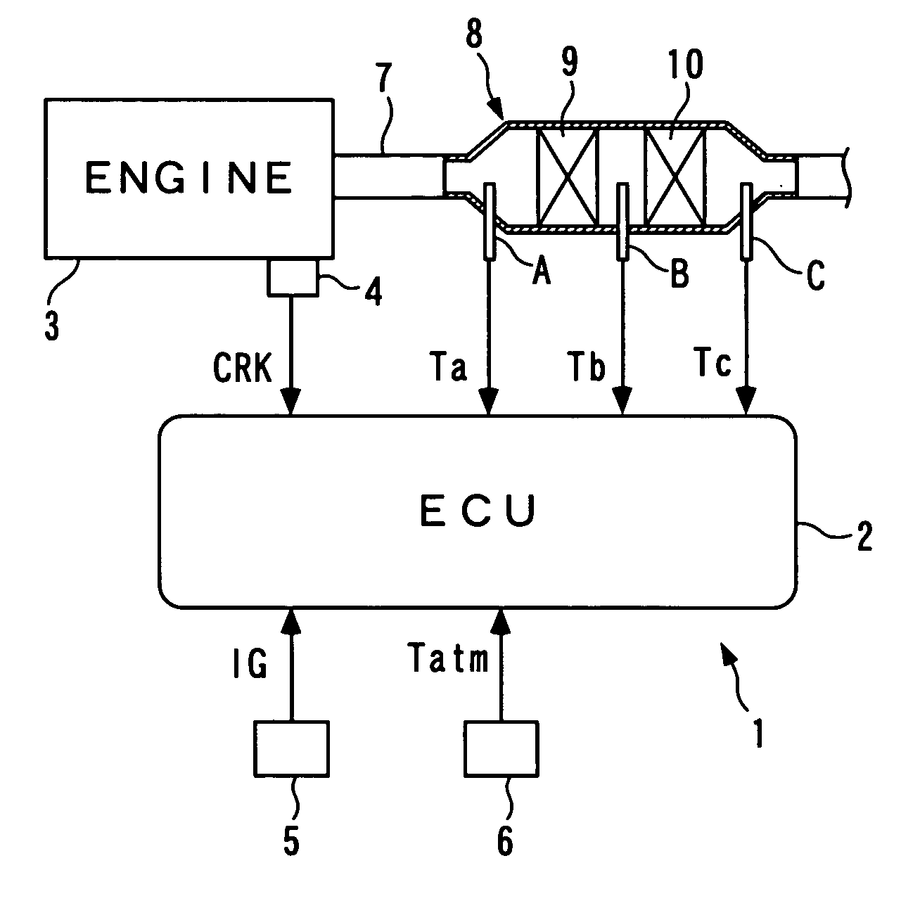
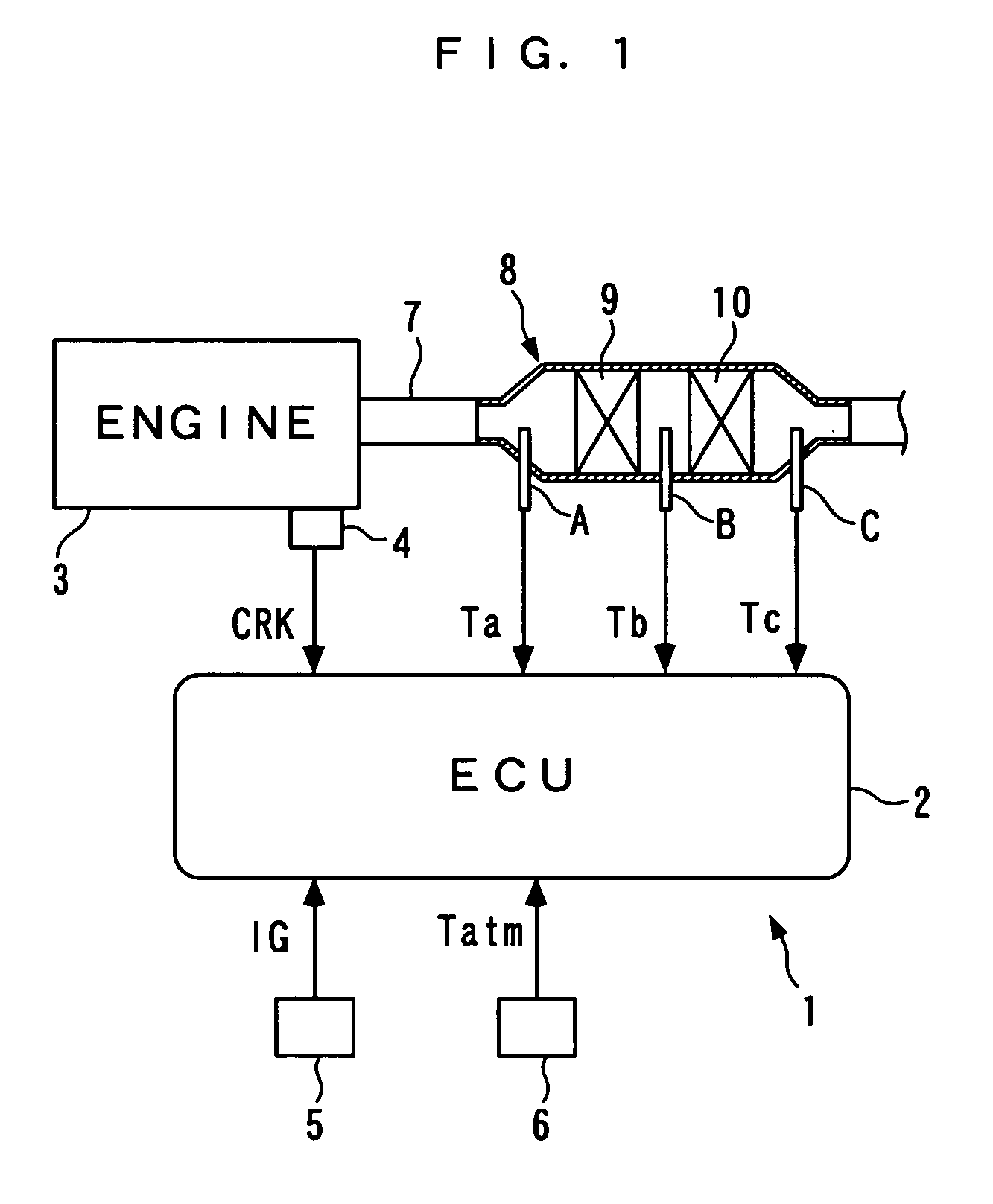
[0031] The present invention will now be described in detail with reference to the drawings showing preferred embodiments thereof. Referring first to FIG. 1, there is schematically shown the arrangement of a failure determination system for a plurality of temperature sensors, according to an embodiment of the present invention, and an internal combustion engine to which the failure determination system is applied. As shown in FIG. 1, the failure determination system 1 includes an ECU 2, and determines failures of three exhaust gas temperature sensors A, B, and C (temperature sensors) that detect temperatures of exhaust gases emitted from the internal combustion engine (hereinafter simply referred to as “the engine”) 3.

[0032] The engine 3 is a diesel engine having e.g. four cylinders, with a crank angle sensor 4 mounted in its body. The crank angle sensor 4 is implemented by a combination e.g. of a magnet rotor and an MRE pickup, and delivers a CRK signal, for example, which is a pu...


PUM


Abstract

A failure determination system for determining failures of temperature sensors, which is capable of easily and accurately determining failures of the sensors in actual operating temperature ranges thereof, even when the ranges are different from each other. Temperatures detected by exhaust gas temperature sensors are stored as initial temperatures when the engine has stopped. Temperatures detected by the respective sensors after stoppage of the engine are made dimensionless based on the corresponding initial temperatures to thereby calculate dimensionless values. An estimated dimensionless value of a temperature to be detected when each sensor is normal is set in advance as an estimated normal value. Failures of the sensors are determined based on results of comparisons of the dimensionless values with the estimated normal value.

Description

BACKGROUND OF THE INVENTION [0001] 1. Field of the Invention [0002] This invention relates to a failure determination system and method for a plurality of temperature sensors provided in an internal combustion engine, and an engine control unit. [0003] 2. Description of the Related Art [0004] Conventionally, this kind of failure determination system for temperature sensors has been proposed in Japanese Utility Model Publication (Kokoku) No. H05-24033. The failure determination system is provided for determining failures of an intake air temperature sensor for detecting the intake air temperature of the engine, and an engine coolant temperature sensor for detecting the coolant temperature of the engine. More specifically, first, detection values of the intake air temperature and the engine coolant temperature detected by the intake air temperature sensor and the engine coolant temperature sensor, respectively, are sampled at predetermined time intervals for a predetermined time perio...

Claims


Application Information

Patent Timeline
IPC IPC(8): G01D18/00G01K1/14
CPCF02D41/222F02D2200/0802G01K1/026Y02T10/40G01K15/00G01K2205/04G01K13/02
Inventor IZUMIURA, ATSUSHISATO, DAISUKEGOSYO, EISAKU
Owner HONDA MOTOR CO LTD
Learn More