Arrangement structure of air bag device
a technology of arrangement structure and air bag, which is applied in the directions of pedestrian/occupant safety arrangement, vehicular safety arrangment, vehicle components, etc. it can solve the problems of increasing the cost of door lining, affecting the air bag position, and occupying a large space in the door lining, so as to increase the rigidity of the first cover, facilitate the deployment direction of the air bag, and reduce the effect of opening the lid
- Summary
- Abstract
- Description
- Claims
- Application Information
AI Technical Summary
Benefits of technology
Problems solved by technology
Method used
Image
Examples
first embodiment
[0040] The arrangement structure of an air bag device of the present invention is explained below referring to the drawings.
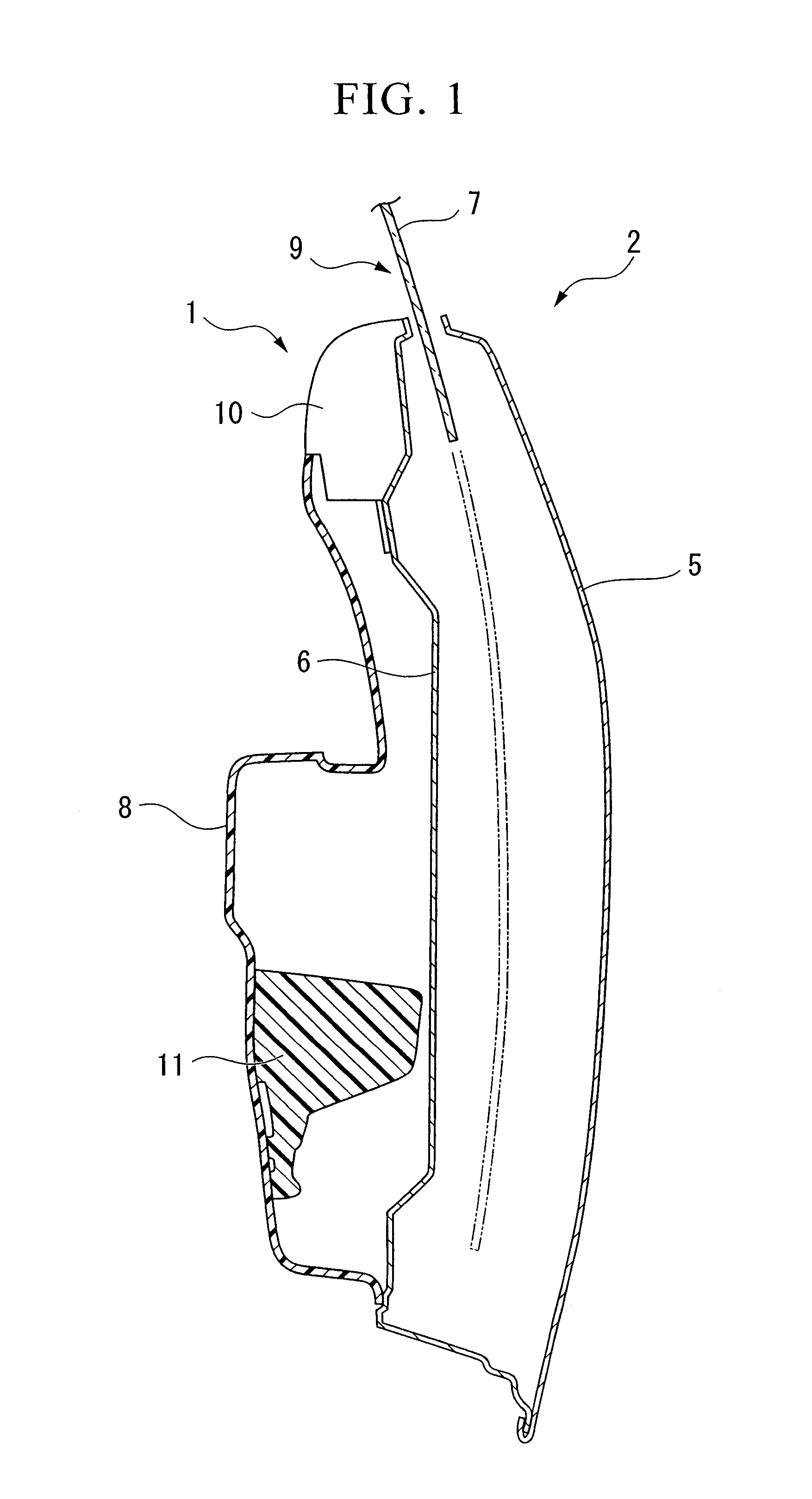
[0041]FIG. 1 schematically shows the cross section of a door 2 on the right side of a vehicle to which the arrangement structure of the air bag device 1 of the present embodiment is applied. In the drawing, the left side of the drawing is the cabin interior side, and the right side of the drawing is the vehicle exterior side. The vehicle to which the air bag device 1 is provided is an open-roof vehicle in which the roof can be opened and closed or is detachable. Note that in the explanation given below, the door 2 is in a closed state.
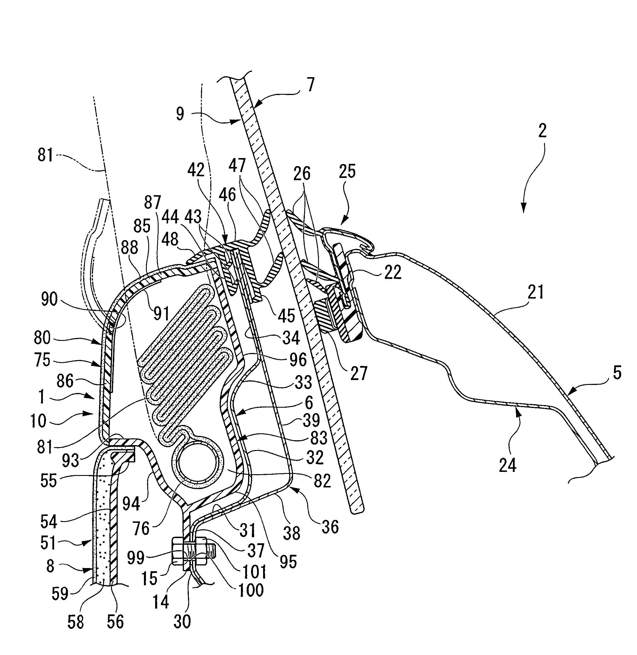
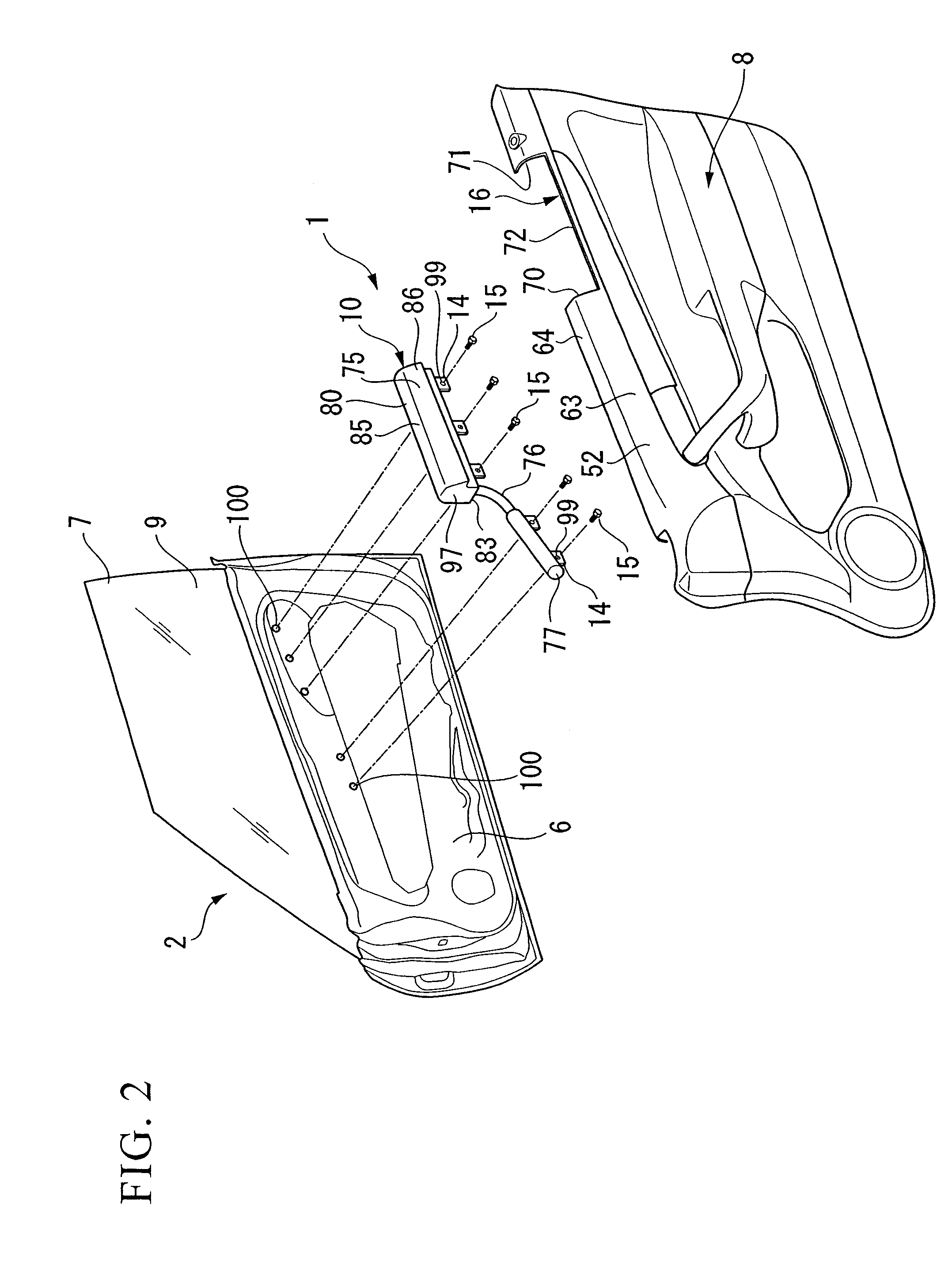
[0042] The door 2 has a metal outer panel 5, a metal inner panel (panel) 6, a window glass 7 that can move up and down, and a door lining (lining) 8. The outer panel 5 is disposed along the vehicle longitudinal direction on the cabin exterior side, and composes the design surface of the cabin exterior side. The inner panel 6 is d...
second embodiment
[0070] In the second embodiment, a stand portion 203, a support projection portion 204, and a flange portion 205 are formed on the top plate portion 185 side of the front plate portion 186. The stand portion 203 projects to the cabin exterior side; the support projection portion 204, which has a shaft shape, projects sideways from the stand portion 203 along the front plate portion 186; and the flat portion 205 projects outward from the distal end of the support projection portion 204 in the diameter direction. A shaft-shaped support projection portion 207 that extends parallel with the support projection portion 204 and a flange portion 208 that projects outward from the distal end of the support projection portion 207 is also formed on the side plate portions 197. A line-shaped strap (regulating member, linear body) 210 that is easily deformable and whose length does not change is hung on the support projection portion 204 of the lid 180 and the support projection portion 207 on t...
third embodiment
[0089] According to the air bag housing portion structure of the third embodiment described above, when the lid 180, which had closed the housing space 82, is opened by being pushed by the deploying air bag 81, as shown in FIG. 12, the upper portion of the lid 180 inclines, centered on the vicinity of the bolt 242, so as to shift the upper portion thereof to the cabin interior side while moving the locking element 245 from the head portion 243 of the bolt 242. At this time, the extension portion 250 of the regulating plate 231 that is provided in the lid 180 moves oppositely to the cabin exterior side to abut the mounting piece 14 of the case body (fixed member) 183. Thereby, the tilting, i.e., opening amount, of the lid 180 is regulated. Accordingly, during deployment of the air bag 81, the lid 180 is prevented from cramping the cabin interior space by more than is needed. Also, since the regulating plate 231 may be made to simply abut the case body 183, the opening amount of the l...
PUM
 Abstract
Description
Claims
Application Information
 - R&D
- Intellectual Property
- Life Sciences
- Materials
- Tech Scout
- Unparalleled Data Quality
- Higher Quality Content
- 60% Fewer Hallucinations
Browse by: Latest US Patents, China's latest patents, Technical Efficacy Thesaurus, Application Domain, Technology Topic, Popular Technical Reports.
© 2025 PatSnap. All rights reserved.Legal|Privacy policy|Modern Slavery Act Transparency Statement|Sitemap|About US| Contact US: help@patsnap.com


