
Method of operating liquid in the vacuum or low-pressure environment and observing the operation and device for the operation and observation

a technology of vacuum or low-pressure environment and liquid operation, applied in the direction of liquid/fluent solid measurement, nuclear engineering, machine/engine, etc., can solve the problems of disabling successful imaging of electron beam or electron diffraction experiment, disabling observation and analysis, and inauthentic observation

Inactive Publication Date: 2007-03-01
CONTREL TECH CO LTD
View PDF5 Cites 9 Cited by
  • Summary
  • Abstract
  • Description
  • Claims
  • Application Information

AI Technical Summary

Benefits of technology

[0014] The secondary objective of the present invention is to provide a method of operating liquid in the vacuum or low-pressure environment and observing the operation, and a device, for the operation and observation, providing an environment for observing liquid without alteration of the original design of the electron microscope.
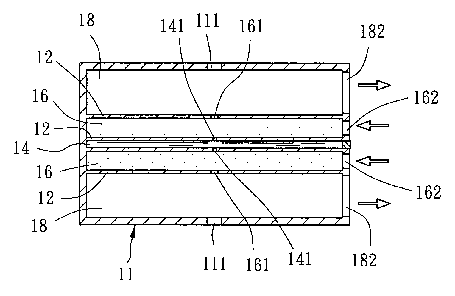
[0018] c) Infuse vapor into the vapor chamber through the gas inlet, and control the vapor pressure inside the vapor chamber to be smaller than or equal to the saturated vapor pressure of the liquid specimen inside the liquid chamber to prevent the liquid inside the liquid chamber from volatilization out of the vapor apertures. The liquid inside the liquid chamber is maintained in a specific amount without loss absolutely or easily. In the meantime, the vapor inside the vapor chamber can slowly leak through the inner apertures into the buffer chamber.
[0019] d) Evacuate the buffer chamber through the pumping ports at a predetermined rate to pump out the vapor exhausted through the inner apertures into the buffer chamber and to prevent the vapor from leaking through the outer apertures out of the housing.

Problems solved by technology

However, such design has the following drawbacks.
However, such entry of supplementary liquid will cause serious problems of flow or uneven admixture of new and original specimens to result in inauthenticity of the observation.
In addition, the massive volatilized high-pressure vapor or the outside high-pressure gas infused into the gas chamber will fill the space (about or more than 1 cm) between the pole pieces to cause a more serious effect of multiple scattering of the electrons resulting from electrons impinging the gasiform molecules, further disabling successful imaging of the electron beam or experiment of electron diffraction.
In addition, the specimen chamber in design fails to effectively control the amount of the infused liquid, causing excessive thickness of the liquid to further disable penetration of the electron beam through the specimen and thus disabling observation and analysis.
Further, it is necessary to disassemble the primary part of the electron microscope before installing the whole system of Gai's design, such that it hardly possible to mass-produce the system.
However, such design tends to cause the multiple scattering of the electrons due to thick window film disabling successful imaging of the electron beam or experiment of electron diffraction.
Further, if the pressure difference between the window-type specimen and the specimen chamber is too high, the window film is subject to rupture causing immediate volatilization of the liquid inside the specimen chamber and contamination of the vacuum area in the electron microscope, resulting in further malfunction or damage of the electron microscope.

Method used


Image

  • Method of operating liquid in the vacuum or low-pressure environment and observing the operation and device for the operation and observation
  • Method of operating liquid in the vacuum or low-pressure environment and observing the operation and device for the operation and observation
  • Method of operating liquid in the vacuum or low-pressure environment and observing the operation and device for the operation and observation

Examples


Embodiment Construction

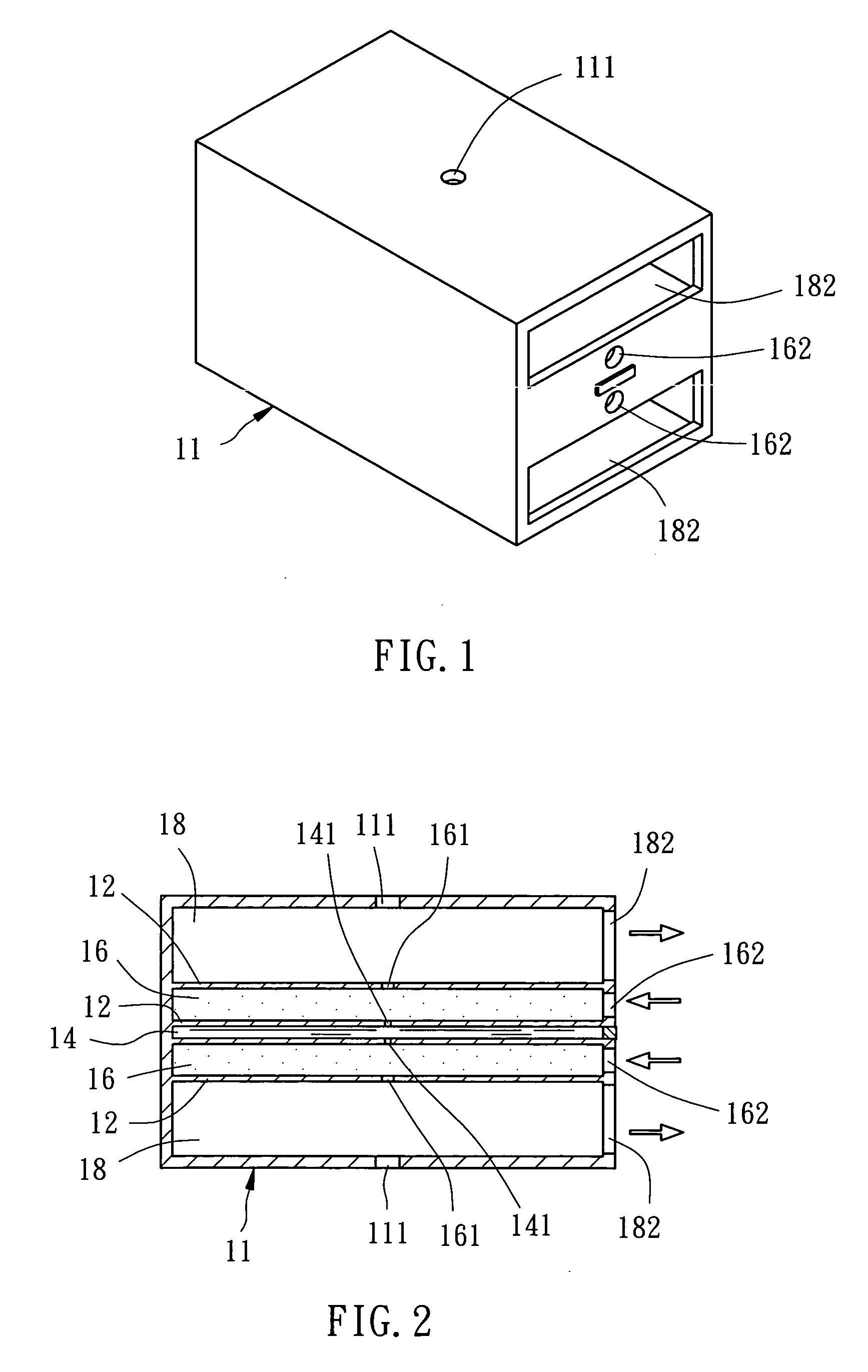
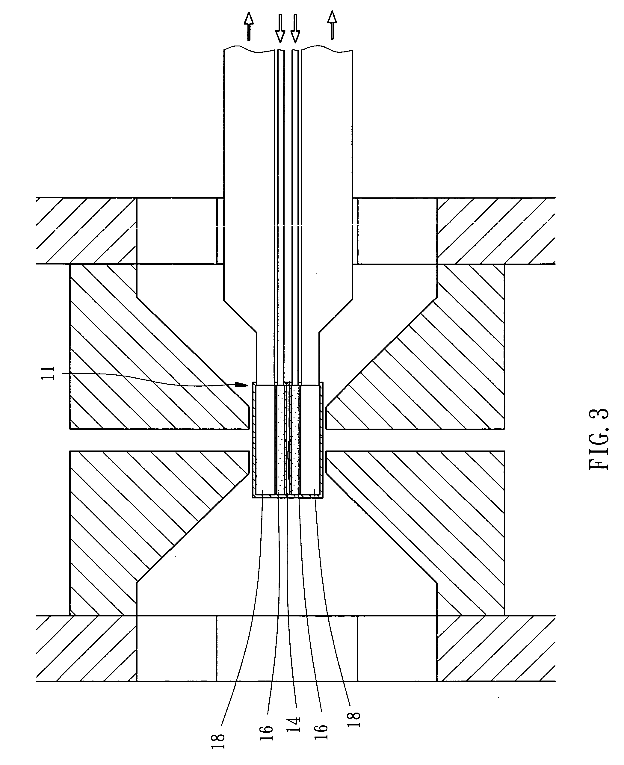
[0036] Referring to FIGS. 1-3, a method of operating liquid in the vacuum or low-pressure environment and observing the operation in accordance with a first preferred embodiment of the present invention includes steps as follows.

[0037] A. Prepare a housing 11, as shown in FIGS. 1 and 2. The housing 11 has a plurality of spacers 12 partitioning off its inside into a liquid chamber 14, two (upper and lower) vapor chambers 16 formed respectively above and below the liquid chamber 14, and two buffer chambers 18 formed respectively above and below the upper and lower vapor chambers 16. The liquid chamber 14 is smaller than 30 μm in height, and is adapted to contain water or a liquid specimen. Each of the spacers 12 located above and below the liquid chamber 14 has a vapor aperture 141. Each of the spacers 12 located respectively above the upper vapor chamber 16 and below the lower vapor chamber 16 has an inner aperture 161. The two inner apertures 161 are located respectively above and ...


PUM

PropertyMeasurementUnit
temperatureaaaaaaaaaa
pressureaaaaaaaaaa

Abstract

A method of operating liquid in a vacuum or low-pressure environment and observing the operation and a device for the operation and the observation respectively, including the steps of preparing a housing, putting the housing in the vacuum or low-pressure environment and keep a predetermined temperature difference between liquid, vapor, and buffer chambers, infusing vapor into the vapor chamber through a gas inlet and control the vapor pressure inside the vapor chamber to be equal to the saturated vapor pressure of a liquid specimen inside the liquid chamber under the same temperature to prevent the inside liquid from volatilization, and evacuating the buffer chamber through the pumping port to pump out the vapor and prevent the vapor from exhausting through outer apertures out of the housing. A probing source can pass through the outer, inner, and vapor apertures for observation and analysis of the liquid specimen inside the liquid chamber.

Description

CROSS REFERENCE TO RELATED APPLICATIONS [0001] The present application is a continuation-in-part of U.S. application Ser. No. 11 / 216,044 entitled METHOD OF OPERATING LIQUID IN THE VACUUM OR LOW-PRESSURE ENVIRONMENT AND OBSERVING THE OPERATION AND DEVICE FOR THE OPERATION AND OBSERVATION filed on Sep. 1, 2005, the disclosure of which is incorporated herein by reference.BACKGROUND OF THE INVENTION [0002] 1. Field of the Invention [0003] The present invention relates generally to the technology of operating liquid substance in the vacuum, and more particularly, to a method of operating liquid in the vacuum or low-pressure environment and observing the operation and a device for the operation and the observation. [0004] 2. Description of the Related Art [0005] As far as the technology of microscopic observation is concerned, it is known that a user can employ an electron microscope with its high-power magnification to do scientific research of nanometer substances. [0006] A conventional...

Claims


Application Information

Patent Timeline
Patent Type & Authority Applications(United States)
IPC IPC(8): H01J37/18
CPCH01J2237/2003H01J37/20
Inventor CHAO, CHIH-YUHSIEH, WEN-JIUNN
Owner CONTREL TECH CO LTD
Learn More