Watercraft steering assist system

a technology for steering assist and watercraft, applied in the direction of propulsive elements, marine propulsion, vessel construction, etc., can solve the problem of difficulty in precise recall for the rider, and achieve the effect of easy anticipating

Inactive Publication Date: 2007-02-08
YAMAHA MOTOR CO LTD
View PDF22 Cites 6 Cited by
  • Summary
  • Abstract
  • Description
  • Claims
  • Application Information

AI Technical Summary

Benefits of technology

[0007] An aspect of at least one of the inventions disclosed herein includes the realization that where thrust of a vehicle is changed based on whether or not the steering mechanism is positioned beyond a predetermined angle, it can be difficult for a rider of such a watercraft to anticipate when the additional thrust will be triggered. For example, as noted above, certain watercraft are provided with a controller that provides additional thrust when the handlebar of the watercraft is turned beyond a predetermined position and when the throttle is released. However, it can be difficult for a rider to remember precisely at what position of the handlebar will the additional thrust be triggered. Thus, one aspect of at least one of the inventions disclosed herein provides a tactile signal to a rider at the position at which additional thrust is triggered. Thus, a rider can more easily anticipate when additional thrust will be provided.
[0008] Another aspect of at least one of the inventions disclosed herein includes the realization that the force that a rider applies to a steering member can be used to control thrust, so as to make turning maneuvers easier to perform. For example, a watercraft can include a sensor to detect the force applied to the handlebar or steering wheel thereof, and a controller can adjust the thrust generated by the propulsion system in accordance with the detected force. When the additional thrust is triggered, the watercraft will turn more. Thus, the watercraft takes on a more intuitive operational characteristic, i.e., the more force applied by the rider, the more the watercraft will turn.

Problems solved by technology

However, it can be difficult for a rider to remember precisely at what position of the handlebar will the additional thrust be triggered.

Method used


Image

  • Watercraft steering assist system
  • Watercraft steering assist system
  • Watercraft steering assist system

Examples


Embodiment Construction

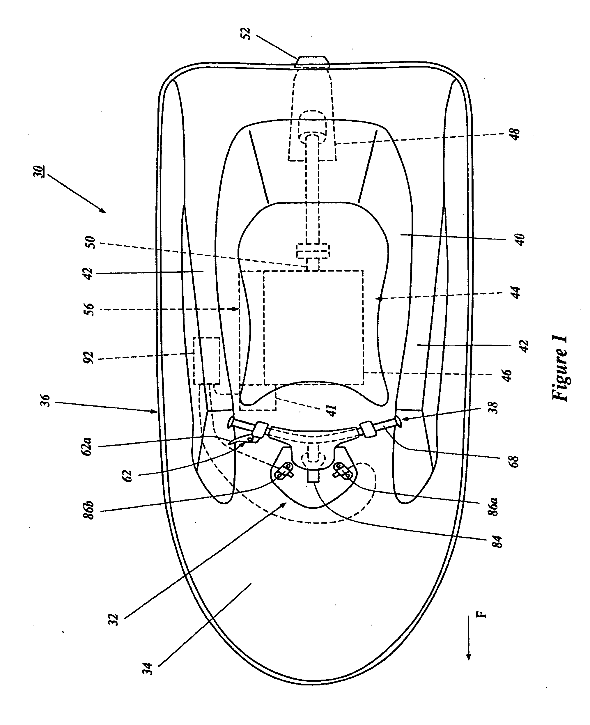
[0037]FIG. 1 illustrates a personal watercraft, generally indicated by the reference numeral 30, which includes a steering assist system including certain features, aspects and advantages of the present inventions. Although the present steering assist system is illustrated in connection with a personal watercraft, the steering assist system may also be used with other types of watercraft as well, such as, for example, but without limitation, small jet boats, and watercraft employing inboard or outboard propeller-type motors.

[0038] Before describing the present steering system, an exemplary personal watercraft 30 is described in general detail to assist the reader's understanding of a preferred environment of use of the present steering system. The watercraft is described in relation to a coordinate system wherein a longitudinal axis extends along a length of the watercraft 30. A central, vertical plane generally bisects the watercraft 30 and contains the longitudinal axis. A latera...


PUM


Abstract

A steering assist system for a watercraft including a force detection assembly adapted to detect a force further applied to an operator steering control of the watercraft after the steering control is turned to a maximum turning position. The steering assist system also includes a controller configured to increase a steering force produced by the watercraft in response to an output of the force detection assembly. In one arrangement, the steering assist system increases an output of a propulsion system of the watercraft in proportion to an output of the force detection assembly. In another arrangement, the steering assist system moves a steering force producing member, such as a deflector or rudder, for example, in response to an output of the force detection assembly in addition to, or alternative to, increasing an output of the propulsion system.

Description

RELATED APPLICATIONS [0001] The present application is related to, and claims priority from, U.S. Provisional Patent Application No. 60 / 458,068, filed Mar. 26, 2003 and Japanese Patent Application Nos. 2002-263681, filed Sep. 10, 2002, and 2003-165262, filed Jun. 10, 2003, the entireties of which are expressly incorporated by reference herein.BACKGOUND OF THE INVENTION [0002] 1. Field of the Invention [0003] The present application generally relates to steering systems for watercraft. More particularly, the present invention relates to a steering assist system for a watercraft. [0004] 2. Description of the Related Art [0005] Many types of watercraft are at least partially dependent upon a power output from an associated propulsion system to develop a steering force in order to steer the watercraft. As a result, steering of the watercraft may become difficult in situations where the engine speed, and thus the output of the propulsion unit, is low, such as when performing docking mane...

Claims


Application Information

Patent Timeline
Patent Type & Authority Applications(United States)
IPC IPC(8): B63H21/22B63H23/00B63H11/113B63H25/20B63H25/42
CPCB63H25/20B63H11/113
Inventor MIZUNO, YUTAKANAKASE, RYOICHIYANAGIHARA, TSUIDE
Owner YAMAHA MOTOR CO LTD
Why Eureka
Try Eureka