
Keypad and manufacturing method thereof

a manufacturing method and keypad technology, applied in the direction of emergency actuators, electrical devices, legends, etc., can solve the problems of poor clarity, difficult to achieve metal luster on the surface, deterioration of the clarity of imprinted words or patterns, etc., and achieve the effect of improving light transmission uniformity

Inactive Publication Date: 2007-02-01
SPEED TECH
View PDF0 Cites 8 Cited by
  • Summary
  • Abstract
  • Description
  • Claims
  • Application Information

AI Technical Summary

Benefits of technology

[0009] Accordingly, at least one objective of the present invention is to provide a method of fabricating a keypad having a better light transmitting uniformity.
[0010] At least another objective of the present invention is to provide a keypad with a better light transmitting uniformity.
[0023] In brief, the keypad of the present invention is fabricated using a metallic sheet. Therefore, it has a metallic luster and a solid three-dimensional metallic feeling. Furthermore, the method of fabricating the keypad includes disposing a light-emitting device layer on the protruding point layer to serve as a planar light source for illuminating the keypad uniformly. Hence, any non-uniformity in the light leaking from the hollow pattern structures is avoided and a better illuminating range is provided. Ultimately, the keypad of the present invention has a better light transmitting uniformity.

Problems solved by technology

In general, although a plastic keypad can still be decorated after performing treatments such as color spraying and laser etching, a metallic luster on the surface is difficult to achieve.
Furthermore, their clarity becomes poor.
As a result, the clarity of the imprinted words or patterns will be deteriorated.

Method used


Image

  • Keypad and manufacturing method thereof
  • Keypad and manufacturing method thereof
  • Keypad and manufacturing method thereof

Examples


Embodiment Construction

[0032] Reference will now be made in detail to the present preferred embodiments of the invention, examples of which are illustrated in the accompanying drawings. Wherever possible, the same reference numbers are used in the drawings and the description to refer to the same or like parts.

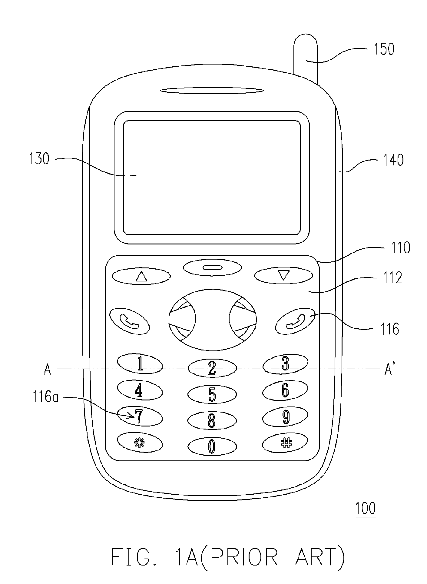
[0033]FIG. 2 is a perspective view of a patterned metallic sheet. FIGS. 3A through 3E are schematic cross-sectional views showing the steps for forming a keypad according to one preferred embodiment of the present invention. As shown in FIGS. 2 and 3A, the method of fabricating a keypad according to the present embodiment includes providing a patterned metallic sheet 210. The method of fabricating the patterned metallic sheet 210 includes providing a standard uncut metallic sheet (not shown) and performing an etching or cutting operation to pattern the metallic sheet. The patterned metallic sheet 210 has a front surface 212 and a rear surface 214 and includes a plurality of independently operated k...


PUM


Abstract

A method for manufacturing a keypad is provided. First, a patterned metallic sheet is provided. This patterned metallic sheet has a front surface and a rear surface and includes a plurality of key units that can be operated independently. These key units have a plurality of hollow structures thereon. Then, an adhesion-enhancing layer is formed on the rear surface of the patterned metallic sheet. Next, a color layer is formed on the adhesion-enhancing layer. A protruding point layer is formed on the adhesion-enhancing layer to cover the color layer. The protruding point layer has a plurality of protruding points that correspond to the positions of the key units. Finally, a light emitting device layer is disposed on the protruding point layer. The keypad manufactured according the disclosed method has a better light transmitting uniformity.

Description

CROSS-REFERENCE TO RELATED APPLICATION [0001] This application claims the priority benefit of Taiwan application serial no. 94125381, filed on Jul. 27, 2005. All disclosure of the Taiwan application is incorporated herein by reference. BACKGROUND OF THE INVENTION [0002] 1. Field of the Invention [0003] The present invention relates to a keypad and manufacturing method thereof. More particularly, the present invention relates to a keypad with a better light transmitting uniformity and the manufacturing method thereof. [0004] 2. Description of the Related Art [0005] In this information explosion era, electronic devices have become an indispensable part of our life. In particular, various portable electronic devices including the mobile phones and the personal digital assistants (PDA) are used almost every day. To attract more consumers, the outward appearance and design of portable electronic devices are constantly changing. Although most consumers will definitely consider the price a...

Claims


Application Information

Patent Timeline
IPC IPC(8): H01H13/70
CPCH01H13/705H01H13/83H01H2209/002H01H2233/052H01H2219/037H01H2221/036H01H2221/074H01H2209/07
Inventor LIU, DEAN-KUOWU, LU-CHIN
Owner SPEED TECH
Learn More