
Image coding apparatus with segment classification and segmentation-type motion prediction circuit

a motion prediction circuit and image coding technology, applied in the field of image coding apparatuses, can solve the problems of large detection errors, unrealistic, and inability to improve the efficiency of coding in the conventional image coding apparatus, and achieve the effect of improving the efficiency of coding

Inactive Publication Date: 2007-01-18
MITSUBISHI ELECTRIC CORP
View PDF12 Cites 40 Cited by
  • Summary
  • Abstract
  • Description
  • Claims
  • Application Information

AI Technical Summary

Benefits of technology

The present invention provides an image coding apparatus and a segmentation-type motion prediction circuit that can improve coding efficiency and motion prediction accuracy. The image coding apparatus can change the coding parameters for each segment based on the content of the image and the memory has a smaller prediction error. The motion prediction circuit can accurately predict motion vectors and produce a prediction image signal with a smaller prediction error. The image coding apparatus and the motion prediction circuit can be used in image coding and decoding processes.

Problems solved by technology

Therefore, the efficiency of coding cannot be improved in the conventional image coding apparatus.
Therefore, detection errors become large when the motion is large.
In the case of real-time communication of moving images, this requires that motion vectors of each segment of an input image be measured automatically at high speed with high accuracy, which is not realistic.
Still further, there is no criterion to judge whether optimum segments have been obtained for the motion vectors detecting operation.
Therefore, the prediction error of an image cannot be made smaller than a block.

Method used


Image

  • Image coding apparatus with segment classification and segmentation-type motion prediction circuit
  • Image coding apparatus with segment classification and segmentation-type motion prediction circuit
  • Image coding apparatus with segment classification and segmentation-type motion prediction circuit

Examples


embodiment 1

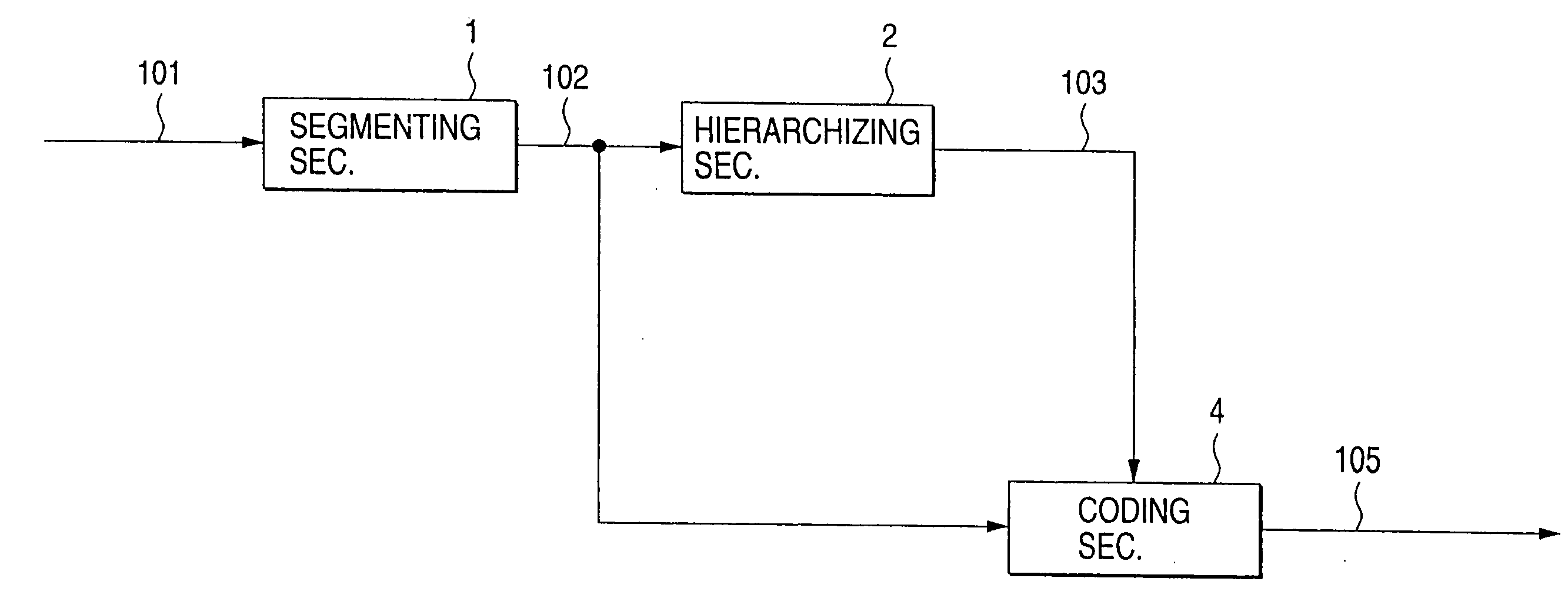
[0082]FIG. 1 is a block diagram showing an image coding apparatus according to a first embodiment of the invention. As shown in FIG. 1, first an input digital image signal 101 to be coded is input to a segmenting section 1. Having an image storage memory such as a frame memory, the segmenting section 1 develops an input image on the memory based on the input image signal 101 of one frame, and dividing the thus-developed input image into a plurality of segments by utilizing, for instance, a particular shape included in the image.

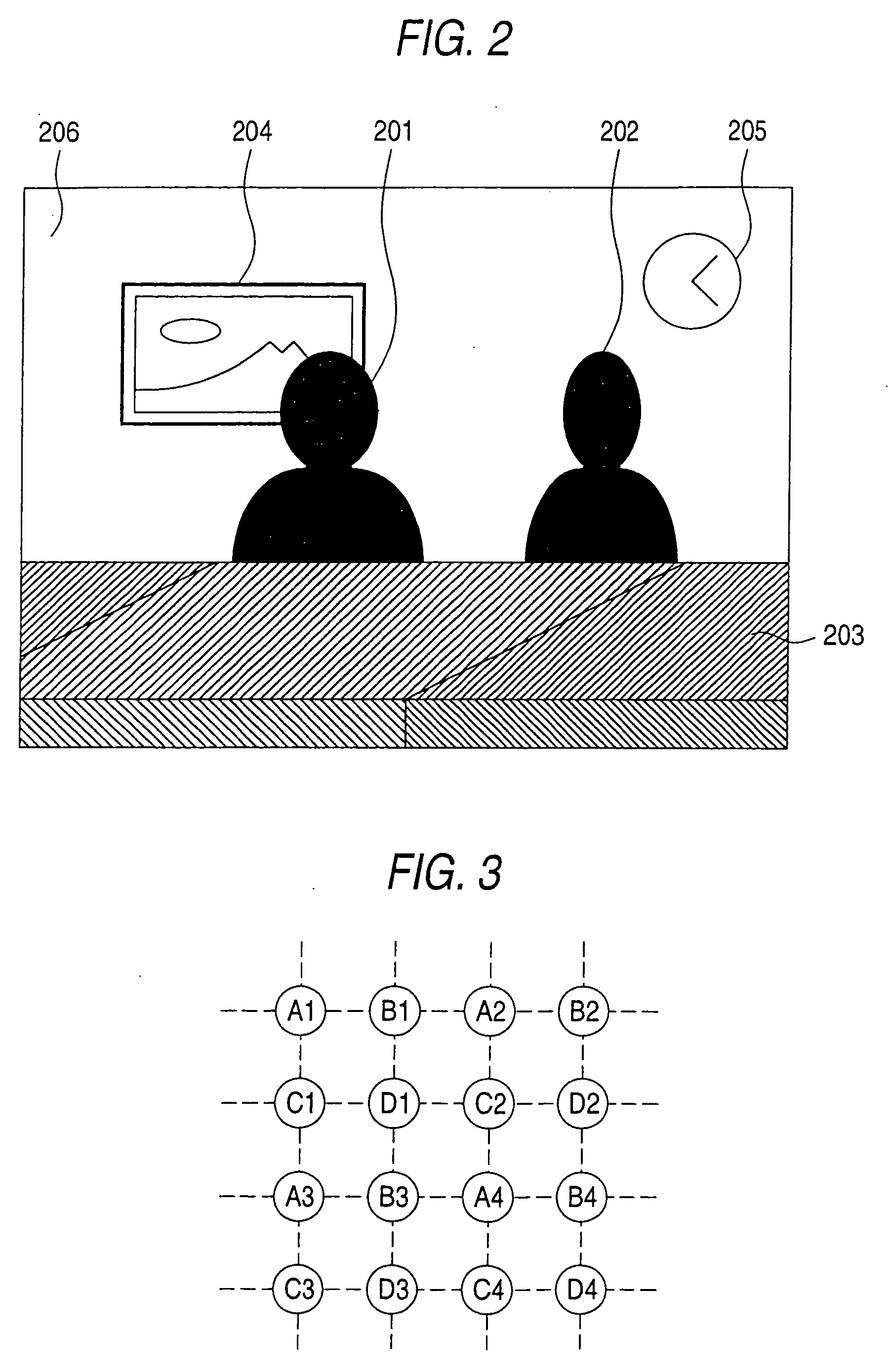
[0083] An example of a segmentation technique is such that edges of an input image are detected by, for instance, differentiating the input image developed on the image storage memory and a portion of the input image enclosed by the edges is made one segment. For example, where the apparatus under discussion is applied to teleconferencing, an image consisting of persons and a background as shown in FIG. 2 is generally given as an input image. By segmenting t...

embodiment 2

[0106]FIG. 4 is a block diagram showing an image coding apparatus according to a second embodiment of the invention.

[0107] While in the first embodiment the value of the coding control parameter in the coding section 4 is changed in accordance with the class of a segment being coded, in the second embodiment a plurality of coding sections of different coding schemes are used and one of the coding sections is selected in accordance with the class of a segment.

[0108] In FIG. 4, the segmenting section 1 and the hierarchizing section 2 operate in the same manner as in the first embodiment.

[0109] Coding sections 4a-4c employ different coding schemes. For example, the coding section 4a performs coding which generates a large amount of code data but allows production of a lossless decoded signal. The coding section 4b performs coding which reduces the amount of generated code data to some extent by conducting quantization, for instance. The coding section 4c performs very rough coding i...

embodiment 3

[0115]FIG. 5 is a block diagram showing an image coding apparatus according to a third embodiment of the invention.

[0116] In this embodiment, the control in accordance with the class of each segment is applied to interframe-prediction-based coding. As is known in the art, in the interframe-prediction-based coding, a prediction signal is generated by predicting an image of the current frame from an image of a past frame stored in a memory, a prediction error signal is calculated from the prediction signal and an actual input image signal by, for instance, taking a difference therebetween, and the prediction error signal is encoded and output. In the decoding side, a similar apparatus for calculating a prediction signal is provided, and a decoded signal is produced by adding the prediction error signal that is sent from the coding side to the prediction signal.

[0117] In FIG. 5, the segmenting section 1 and the hierarchizing section 2 operate in the same manner as in the first embodi...


PUM


Abstract

A segmenting section divides an input image into a plurality of segments. A hierarchizing section determines classes of the respective segments according to a predetermined criterion, and produces a class identification signal indicating the classes of the respective segments. A coding section encodes the segmented image signal into code data while changing the value of a coding control parameter for each of the segments in accordance with the class identification signal. Examples of the coding control parameter are a coding time interval and precision of quantization.

Description

[0001] This application is a Divisional of application Ser. No. 11 / 360,510, filed on Feb. 24, 2006; which is a Divisional of application Ser. No. 10 / 879,192, filed on Jun. 30, 2004, now abandoned; which is a Divisional of application Ser. No. 09 / 436,258, filed on Nov. 9, 1999, now U.S. Pat. No. 6,798,834, issued on Sep. 28, 2004; which is a Divisional of application Ser. No. 08 / 915,590, filed on Aug. 21, 1997, now abandoned; which is a Divisional of application Ser. No. 08 / 698,417 filed on Aug. 15, 1996, now abandoned. The entire contents of all of the aforementioned applications are incorporated by reference.BACKGROUND OF THE INVENTION [0002] 1. Field of the Invention [0003] The present invention relates to an image coding apparatus which is used in image communications equipment for, for instance, visual telephone and teleconferencing and image storage / recording equipment such as a digital VTR. [0004] The invention also relates to a motion prediction circuit which performs motion ...

Claims


Application Information

Patent Timeline
Patent Type & Authority Applications(United States)
IPC IPC(8): H04N7/12H04B1/66H04N7/26
CPCH04N19/105H04N19/543H04N19/46H04N19/115H04N19/61H04N19/117H04N19/12H04N19/124H04N19/127H04N19/132H04N19/14H04N19/137H04N19/17H04N19/20H04N19/23H04N19/537H04N19/176
Inventor MURAKAMI, TOKUMICHIASAI, KOHTAROYAMADA, YOSHIHISAFUKUHARA, TAKAHIRO
Owner MITSUBISHI ELECTRIC CORP
Learn More