
Self-centering straddling harvesting head for small fruit harvesting machine and machine equipped with such harvesting head

a harvesting head and straddling technology, which is applied in the direction of digger harvesters, topping machines, picking devices, etc., can solve the problems of unbalance the pendulum, unbalance the pendulum, and add a very significant inertia when the bins are filled, so as to improve the comfort and simplify the operation of the machin

Active Publication Date: 2007-01-18
PELLENC SA
View PDF17 Cites 22 Cited by
  • Summary
  • Abstract
  • Description
  • Claims
  • Application Information

AI Technical Summary

Benefits of technology

The invention is a harvesting head for a self-propelled harvesting machine that can automatically center itself over the plants in the row, regardless of its weight or position of gravity. The head is dependent on a control system that can impart movements on either side of the machine, allowing it to align itself with the plants. The head can be equipped with mechanical components or hydraulic, pneumatic, or electrical actuators to achieve this centering. The head is also designed to follow the vine row through positional control, making it easier to enter the rows and ensuring high-quality harvests. The invention offers increased travel speed, higher productivity, and improved quality of the harvests.

Problems solved by technology

However, it often happens that whenever the vines are low or not tied, or not very well tied, that the vegetation hanging down onto the ground is very dense and therefore partially or completely hides the vine stocks so that the operator is lacking the necessary reference points to correct the machine offset in relation to the vine row axis.
However, this pendulum guiding system currently used by most self-propelled harvesting machine builders has major disadvantages.
The major problem derived from this system results from the fact that centering is achieved through the reaction of the vine stocks on the lower guide ramps located on the lower part of the harvesting head, usually between the receiving device for the grapes and bunches stripped from the vine stocks (mobile aprons or bucket conveyors) and the ground, the distance between both parallel guide ramps making up the mechanical corridor of said harvesting head.
In addition, a pendulum system makes it necessary to provide for the lowest center of gravity in relation to the pendulum axis, which eliminates the possible mounting of the receiving bins on the swinging assembly, which would cause to add a very significant inertia when the bins are filling.
In addition, the not always even filling of said bins would unbalance the pendulum, which would off-center the mechanical corridor in relation to the vine row.
Such parasitic accelerations are usually perpendicular to the pendulum axis, and the highly undesirable effect thereof is to trigger the guiding of the mechanical corridor but not in the right direction and to create counter-reactions on the vine stocks that may cause their breaking.

Method used


Image

  • Self-centering straddling harvesting head for small fruit harvesting machine and machine equipped with such harvesting head
  • Self-centering straddling harvesting head for small fruit harvesting machine and machine equipped with such harvesting head
  • Self-centering straddling harvesting head for small fruit harvesting machine and machine equipped with such harvesting head

Examples


third embodiment

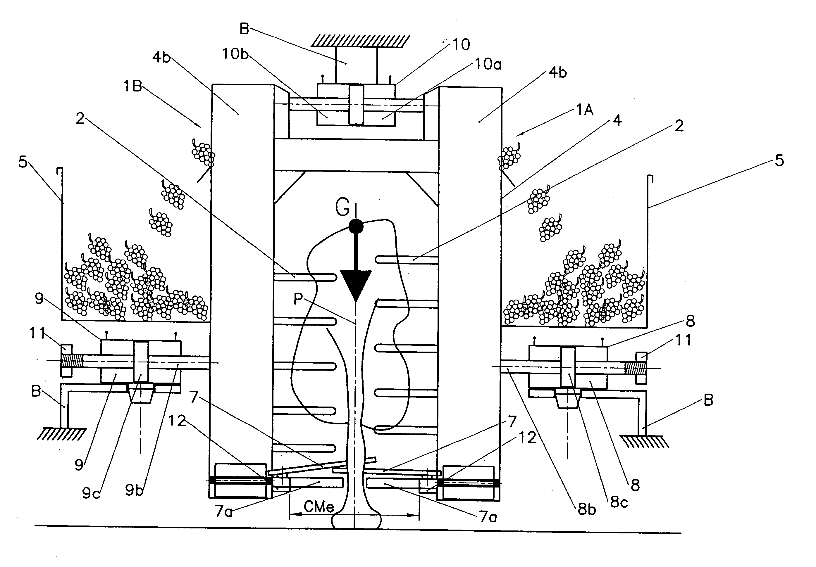
[0088] In FIGS. 5 and 6, a third embodiment is shown, that differs from the one just described, mainly because of a design under which the position sensors placed at the entry of the mechanical CMe of the harvesting head consist of rigid probes 7B, each sensor actuating directly a hydraulic distributor 13 installed close to said sensor. In this figure, the central jack 10 is not shown.

[0089] According to this embodiment, the description of the operation of the jacks 8,9,10 is roughly the same as in the above-described example.

fourth embodiment

[0090]FIG. 7 shows a fourth embodiment according to which the position sensors placed on both sides of the mechanical corridor CMe and in front of it consist of the first pivoting apron 7C of each row of right and left overlapping aprons 2a making up the mobile platform receiving the detached berries.

[0091] These sensor aprons act on an electric contact actuating a hydraulic electro-distributor or actuate directly a hydraulic electro-distributor, as described above.

[0092] Considering that the pivoting aprons 2a making up the mobile platform 2 receiving the harvest are installed symmetrically by pair on both sides of the mechanical corridor CMe, the position sensors could consist of one or more pairs of aprons arranged at a or any distance(s) from the entry of said corridor.

[0093] In addition, according to this embodiment, angular sensors 14 can be placed at the articulation of the sensor aprons 7C so as to be able to measure the kinematical angles A° and B° caused by the offset d ...

first embodiment

[0095] The description of the operation of the guiding hydraulicjack assembly 8, 9, 10 is also in this case the same as for the above-described first embodiment, with the sole exception that the corrective action is proportional to the misalignment of the symmetry axis A of the harvesting head and of the vine stock P according to the distance d that is well known because measured.


PUM


Abstract

Harvesting head to be installed on a traveling carrier and configured to straddle a row of fruit-bearing plants, during operation, so as to harvest berries or small fruit such as, for example, grapes, black currants, gooseberries, raspberries, olives is the present invention. The harvesting head is dependent on one or more a device imparting movements during operation, the movements on either side being in relation to the median vertical plane of a straddling carrier on which the harvesting head is mounted. The device is controlled by at least one control system and capable of centering at least the lower part of the harvesting head in relation to the plants in rows.

Description

RELATED U.S. APPLICATIONS [0001] Not applicable. STATEMENT REGARDING FEDERALLY SPONSORED RESEARCH OR DEVELOPMENT [0002] Not applicable. REFERENCE TO MICROFICHE APPENDIX [0003] Not applicable. FIELD OF THE INVENTION [0004] This invention concerns a self-centering straddling harvesting head for small fruit harvesting machines. [0005] More specifically, it concerns a “self-centering” straddling harvesting head for berry or small fruit harvesting machines, especially for grape harvesting machines of the type made of two sub-assemblies rigidly assembled at their upper part and between which a corridor is provided that allows for their movement on each side of a row of vine stocks or other plants. Each of said sub-assemblies comprising: [0006] a fruit detaching system usually consisting of a shaking device; [0007] a receiving device for the detached fruit most frequently consisting of an articulated platform consisting of inclined and swinging overlapping plates or aprons; [0008] a transp...

Claims


Application Information

Patent Timeline
Patent Type & Authority Applications(United States)
IPC IPC(8): A01D46/00
CPCA01D46/28
Inventor PELLENC, ROGERGIALIS, JEAN-MARC
Owner PELLENC SA
Learn More