
Apparatus and method for deciding in-focus position of imaging lens

an imaging lens and in-focus position technology, applied in the field of imaging lens in-focus position determination, can solve the problems of inability to accurately detect the skin-tone area, inability to accurately focus, and difficulty in accurately detecting the target in an extremely out-of-focus state, and achieve the effect of focusing comparatively accurately

Active Publication Date: 2006-12-28
FUJIFILM CORP
View PDF7 Cites 9 Cited by
  • Summary
  • Abstract
  • Description
  • Claims
  • Application Information

AI Technical Summary

Benefits of technology

[0006] Accordingly, an object of the present invention is to achieve focusing comparatively accurately.
[0010] Since it is attempted to detect the target from the image of the subject obtained in a case where the focusing data is equal to or greater than a prescribed threshold value, it is easier to detect the target accurately. The position of the imaging lens is decided on based upon the image data representing the image of the detected target. The position of the imaging lens can therefore be decided so as to bring the image of the target into focus comparatively accurately.
[0020] In the third aspect of the present invention, second focusing data is obtained in a focusing range in the vicinity of a maximal value and comparatively accurate focusing control can be performed. Moreover, if a maximal value is detected and a target image is detected, no subsequent processing for outputting first focusing data and for detecting maximal value is executed. This makes it possible to decide the in-focus position comparatively quickly.
[0023] It may be so arranged that movement of the imaging lens in the first focusing data output device is performed from the NEAR side. An important target often is on the NEAR side. Detecting the target first, therefore, makes feasible the halting of subsequent processing.
[0027] Distance travelled by the imaging lens in the first focusing data output device may be greater than distance travelled by the imaging lens in the second focusing data output device. By executing processing for outputting the first focusing data coarsely and executing processing to output the second focusing data finely, the position of the imaging lens can be decided quickly and accurately.

Problems solved by technology

Even in a case where a skin-tone area is detected, however, it is difficult to detect the skin-tone area accurately when the very subject image in which the skin tone is to be detected is extremely out of focus.
Consequently, there are occasions where focusing cannot be achieved accurately even when a skin-tone area is adopted as a focusing area.
Similarly, even in a case where a target is detected solely from contrast (density) information without using color information, it is difficult to detect the target accurately in an extremely out-of-focus state.

Method used


Image

  • Apparatus and method for deciding in-focus position of imaging lens
  • Apparatus and method for deciding in-focus position of imaging lens
  • Apparatus and method for deciding in-focus position of imaging lens

Examples


Embodiment Construction

[0049] Preferred embodiments of the present invention will now be described in detail with reference to the drawings.

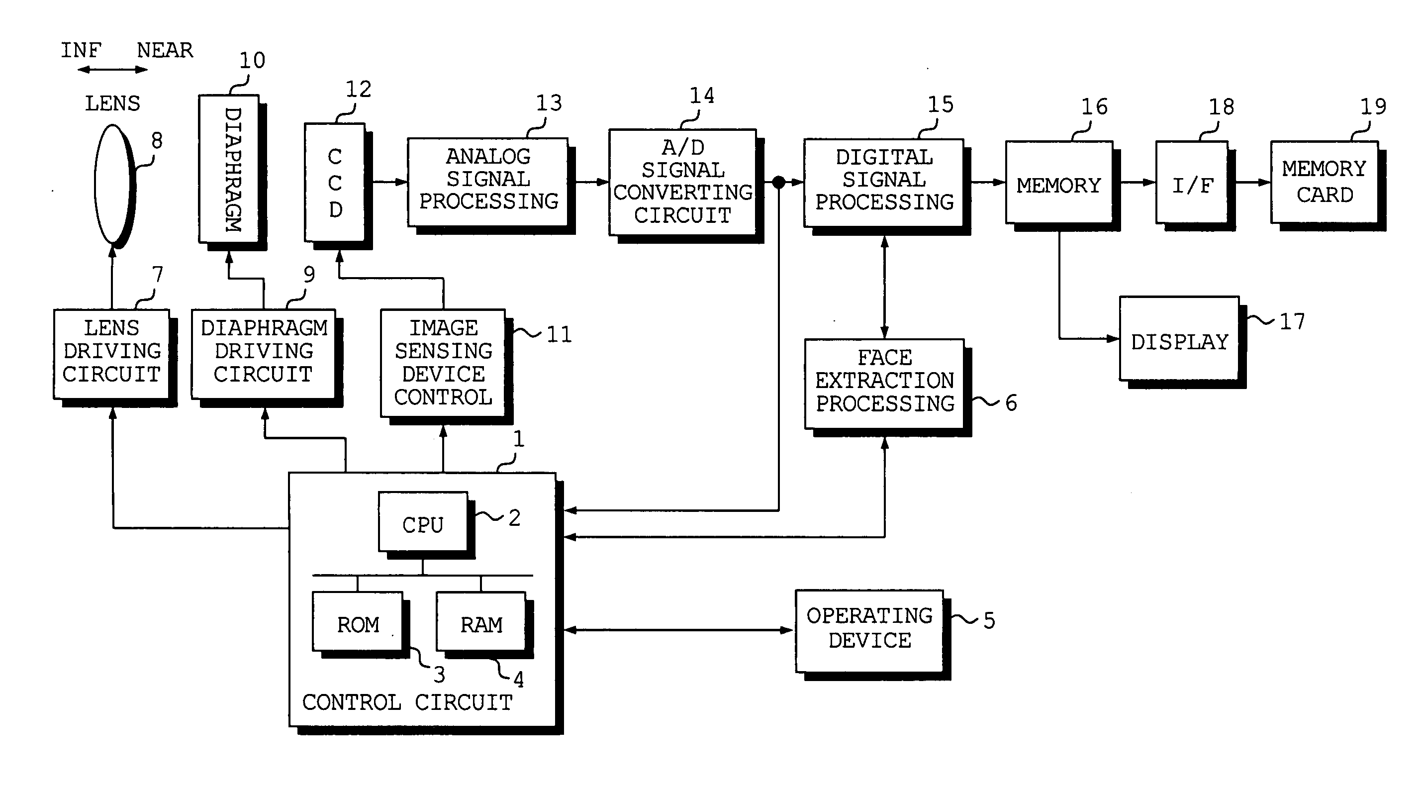
[0050]FIG. 1 is a block diagram illustrating the electrical configuration of a digital still camera according to an embodiment of the present invention.

[0051] The digital still camera according to this embodiment is so adapted that a face in the image of a subject will come into focus in suitable fashion.

[0052] The operation of the overall digital still camera is controlled by a control circuit 1. The control circuit 1 includes a CPU 2, a ROM 3 in which the operating program of the digital still camera and prescribed data, etc., have been stored, and a RAM 4 for storing data temporarily.

[0053] The digital still camera is provided with an operating device 5 having switches and buttons such as a shutter-release button of two-step stroke type. An operating signal that is output from the operating device 5 is input to the control circuit 1.

[0054] A diaphragm 10 and i...


PUM


Abstract

An imaging lens is positioned at an initial position, the image of a subject is sensed and an overall focus evaluation value representing the degree of focus of the image of the subject is obtained. Face detection processing is executed if the overall focus evaluation value obtained is equal to or greater than a threshold value but is not executed if the overall focus evaluation value is less than the threshold value. The imaging lens is then moved to the next position. Calculation of the overall focus evaluation value is performed again and if the overall focus evaluation value is equal to or greater than the threshold value, then face detection processing is executed on this occasion. A range in which face images are detected at positions of the imaging lens where the overall focus evaluation value is equal to or greater than the threshold value is decided upon as a focusing range. The image of the subject is sensed again while the imaging lens is moved in this range in prescribed increments. A graph of face-area focus evaluation values representing degree of focus of the image portion of the face is obtained and the position at which this graph is maximum is decided upon as the in-focus position of the imaging lens.

Description

BACKGROUND OF THE INVENTION [0001] 1. Field of the Invention [0002] This invention relates to a method and apparatus for deciding the in-focus position of an imaging lens. [0003] 2. Description of the Related Art [0004] In an example of the prior art (see the specification of Japanese Patent Application Laid-Open No. 11-146405), a skin-tone area contained in the image of a subject is detected and the skin-tone area detected is adopted as a focusing area. [0005] Even in a case where a skin-tone area is detected, however, it is difficult to detect the skin-tone area accurately when the very subject image in which the skin tone is to be detected is extremely out of focus. Consequently, there are occasions where focusing cannot be achieved accurately even when a skin-tone area is adopted as a focusing area. Similarly, even in a case where a target is detected solely from contrast (density) information without using color information, it is difficult to detect the target accurately in an...

Claims


Application Information

Patent Timeline
Patent Type & Authority Applications(United States)
IPC IPC(8): G06C27/00
CPCG02B7/36
Inventor SUGIMOTO, MASAHIKO
Owner FUJIFILM CORP
Learn More