
Keypad signal input apparatus

a signal input and keypad technology, applied in the field of keypad apparatus, can solve the problem that the processor has a limited number of input pins available, and achieve the effect of improving the accuracy of the signal inpu

Inactive Publication Date: 2006-12-21
NXP USA INC
View PDF9 Cites 11 Cited by
  • Summary
  • Abstract
  • Description
  • Claims
  • Application Information

AI Technical Summary

Benefits of technology

The present invention is about a new type of keypad and data entry system. The technical effects of this invention are not specified in the text, but it can be inferred that it may improve the efficiency and accuracy of data entry.

Problems solved by technology

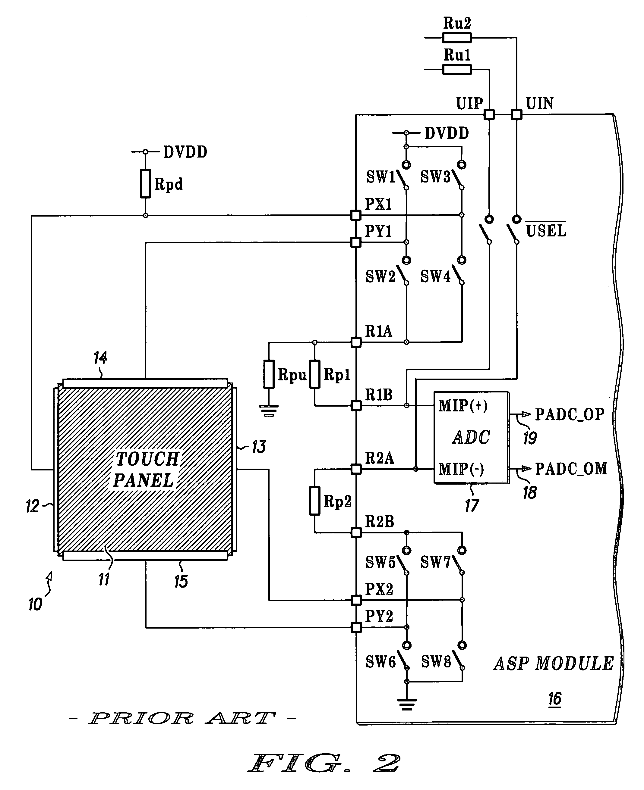
Typically, the signal processor has a limited number of input pins available for each input or output device to which it is connected.

Method used


Image

  • Keypad signal input apparatus
  • Keypad signal input apparatus
  • Keypad signal input apparatus

Examples


Embodiment Construction

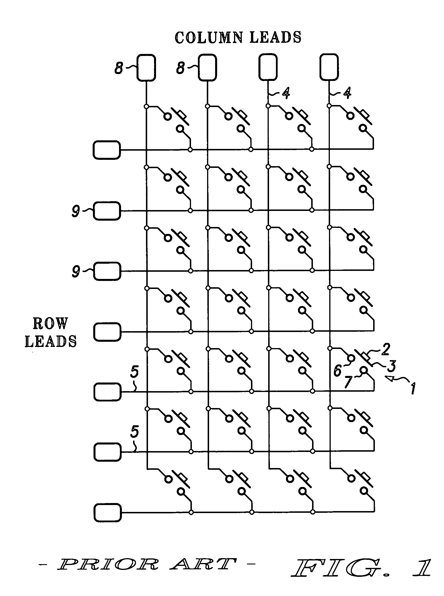
[0018] The keypad shown in FIG. 1 comprises an array of keys or push-button switches 1 each comprising a button 2 projecting through a two-dimensional surface (not shown) and bearing an electrical connection element 3. The keypad also comprises column leads 4 and row leads 5, the switches 1 comprising contact elements 6 connected to individual column leads and contact elements 7 connected to individual row leads. The key 1 is biased mechanically away from the contact element 6 and 7 but connects the contact elements 6 and 7 electrically when actuated by a user pushing the button 2. Connection in this way of the contact elements 6 and 7 of any given push-button switch 1 makes a respective unique connection between a column lead 4 and a row lead 5.

[0019] Each column lead 4 has a corresponding column terminal 8, and each row lead 5 has a corresponding row terminal 9. In this example of a keypad, the array of switches 1 comprises 4 columns and 7 rows, so that there are a total of 11 te...


PUM


Abstract

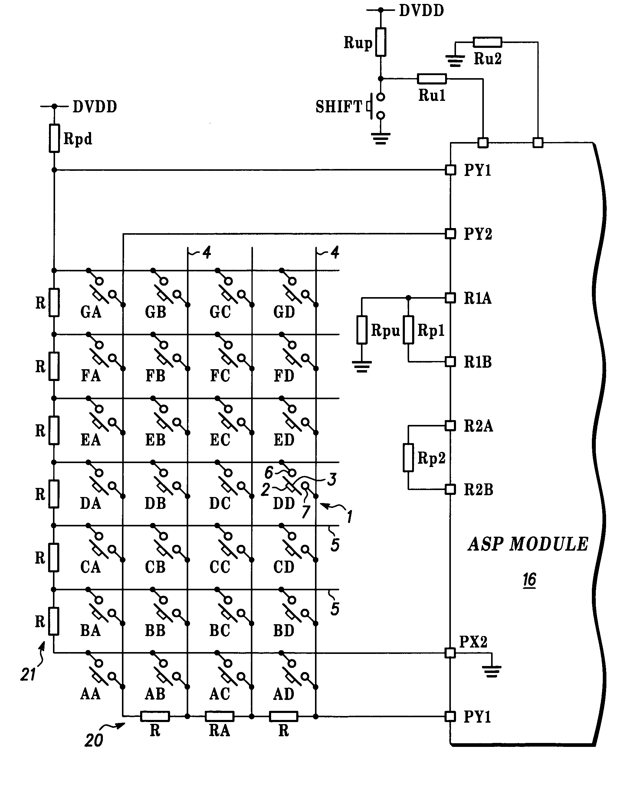
Keypad apparatus for registering signals corresponding to data that a user enters by pressure on keys of an array in a surface extending in two dimensions. The elements of first and second sets of impedance elements (R) are connected in series through respective interconnections and a signal processor applies first and second reference signals across the first and second sets of impedance elements respectively. User pressure on the keys makes or breaks connections through corresponding contact elements between a respective pair of the interconnections, one from the first set of impedance elements and one from the second set of impedance elements, so as to generate first and second output signals (PX1, PY1) that together are a corresponding combination of the first and second reference signals that is unique to the actuated key elements.

Description

FIELD OF THE INVENTION [0001] This invention relates to keypad apparatus for registering signals corresponding to data that a user enters by pressure on discrete features of a surface extending in two dimensions and to data entry apparatus including such keypad apparatus. BACKGROUND OF THE INVENTION [0002] Keypads are used in various devices, including portable telephones and personal digital assistants (‘PDAs’) for example. The discrete features that the user presses to enter data may take various forms, such as push-buttons projecting through the surface or elastic relief on the surface, for example. The number of features will depend on the application that the keypad is used for but typically is of the order of 20 to 40, for example 28 if the features form a 4 by 7 array. [0003] The keypad generates electrical signals, which are then processed by a signal processor. Typically, the signal processor has a limited number of input pins available for each input or output device to wh...

Claims


Application Information

Patent Timeline
Patent Type & Authority Applications(United States)
IPC IPC(8): H03M11/00H03K17/94G06F3/00H03M11/22
CPCG06F3/0338G06F3/045H01H2221/012H03M11/24H01H2239/012H03M11/22H01H2225/018
Inventor KHLAT, NADIM
Owner NXP USA INC
Learn More