
Power ring extension cord system

a power ring and extension cord technology, applied in the field of extension cord systems, can solve the problems of large difficulty in untangling long lighting strands, many and varied, and the entire strand is not lit, and achieves the effects of easy disassembly, assembly and storage, simple and durable, and easy assembly

Inactive Publication Date: 2006-11-23
BEITLER MARTIN M
View PDF2 Cites 2 Cited by
  • Summary
  • Abstract
  • Description
  • Claims
  • Application Information

AI Technical Summary

Benefits of technology

"The invention provides a method for safely and easily providing electrical power to trees and other structures using a power ring extension cord system with electrical power outlets and a cord for supplying power to the outlets. The system allows for attachment of electric light strings, ornaments, and other decorations at multiple levels on the structure. The light strands are shorter and less likely to break, and the system is easy to assemble, disassemble, and store. The invention provides a more versatile and efficient means of electrically decorating trees and structures."

Problems solved by technology

The problems with this present technique are many and varied.
They include older wiring in which the bulbs are in series and even a single blown bulb can lead to the entire strand not lighting, and great difficulty in untangling the long lighting strands while removing them from the tree or from their storage container.
Additionally, designs with the present technique are primarily limited to light bulbs pre-arranged by the long strands, which provide little alternative to simply wrapping the strands around the object (e.g., tree branch) to be illuminated, and with no flexibility as to other forms of signage or display media.
Further, this device can be placed only at the tree's periphery, easily tangles, and can only be used for a tree and not any other structures.
Lastly, it is not clear if it can be used out doors and, due to its cumbersome nature, it cannot be easily stored as may be suggested in that no provision is made for a storage mechanism when it is not in use.
It is difficult to keep the lights in place and there in no adaptability for displaying other devices or signage.
It also has little application or flexibility for use with any other structure besides trees.
The problems with this device are that once deformed to fit a given structure it is more difficult to attach it to a different structure.
The inherent design is carried out specifically to provide the lighting system its own fixed structure which creates redundancy of structure and cumbersomeness of design which in turn limits its adaptability.
This device too seems restrictive in use allowing for no specific use for other holiday occasions.
None of them offer the possibility of use for signage such as building street address designation, or attaching ornaments specific to holidays other than Christmas.
Lastly none offers much flexibility of design, ease of application, or ease of disassembly and storage.

Method used


Image

  • Power ring extension cord system
  • Power ring extension cord system
  • Power ring extension cord system

Examples


Embodiment Construction

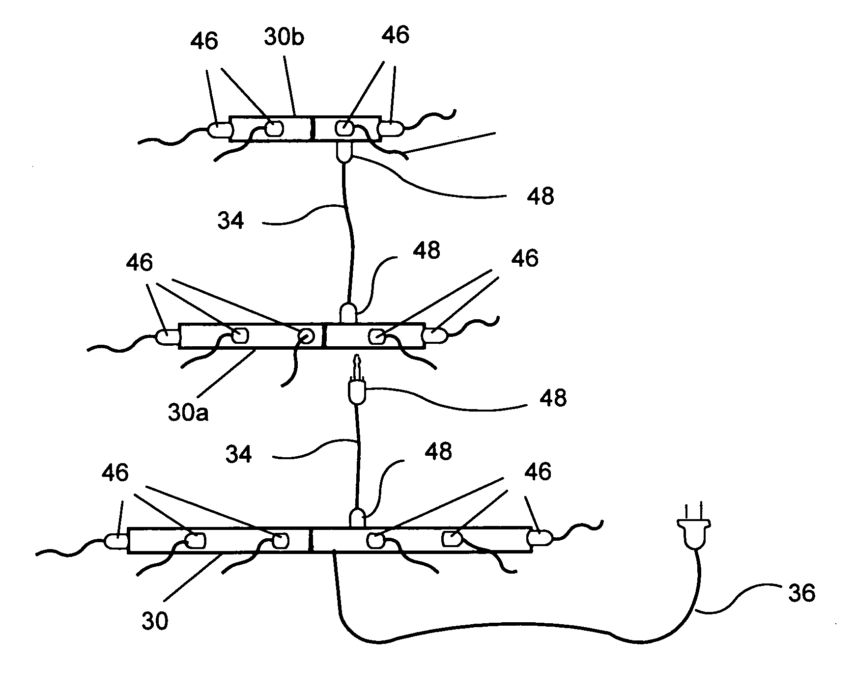
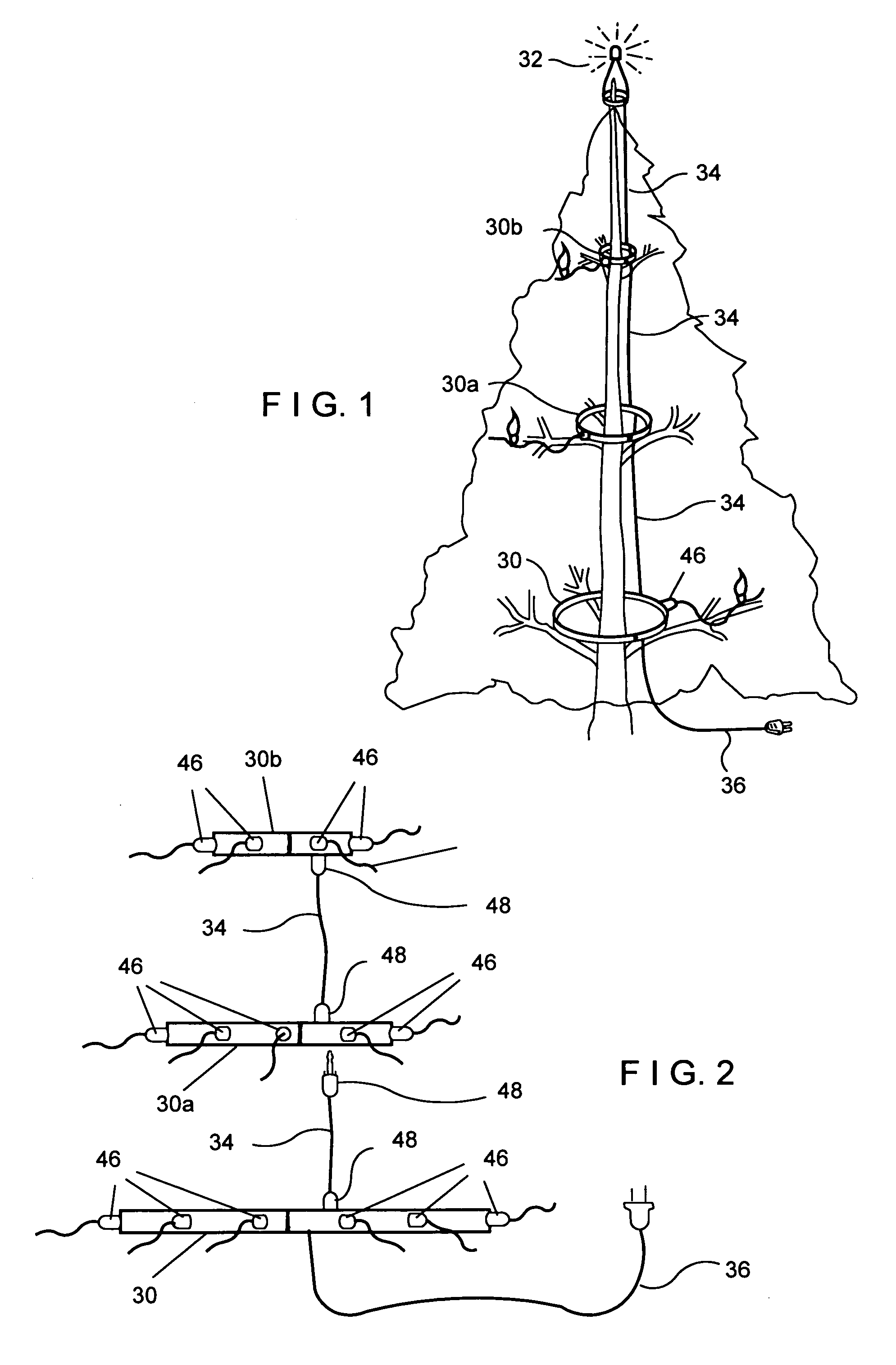
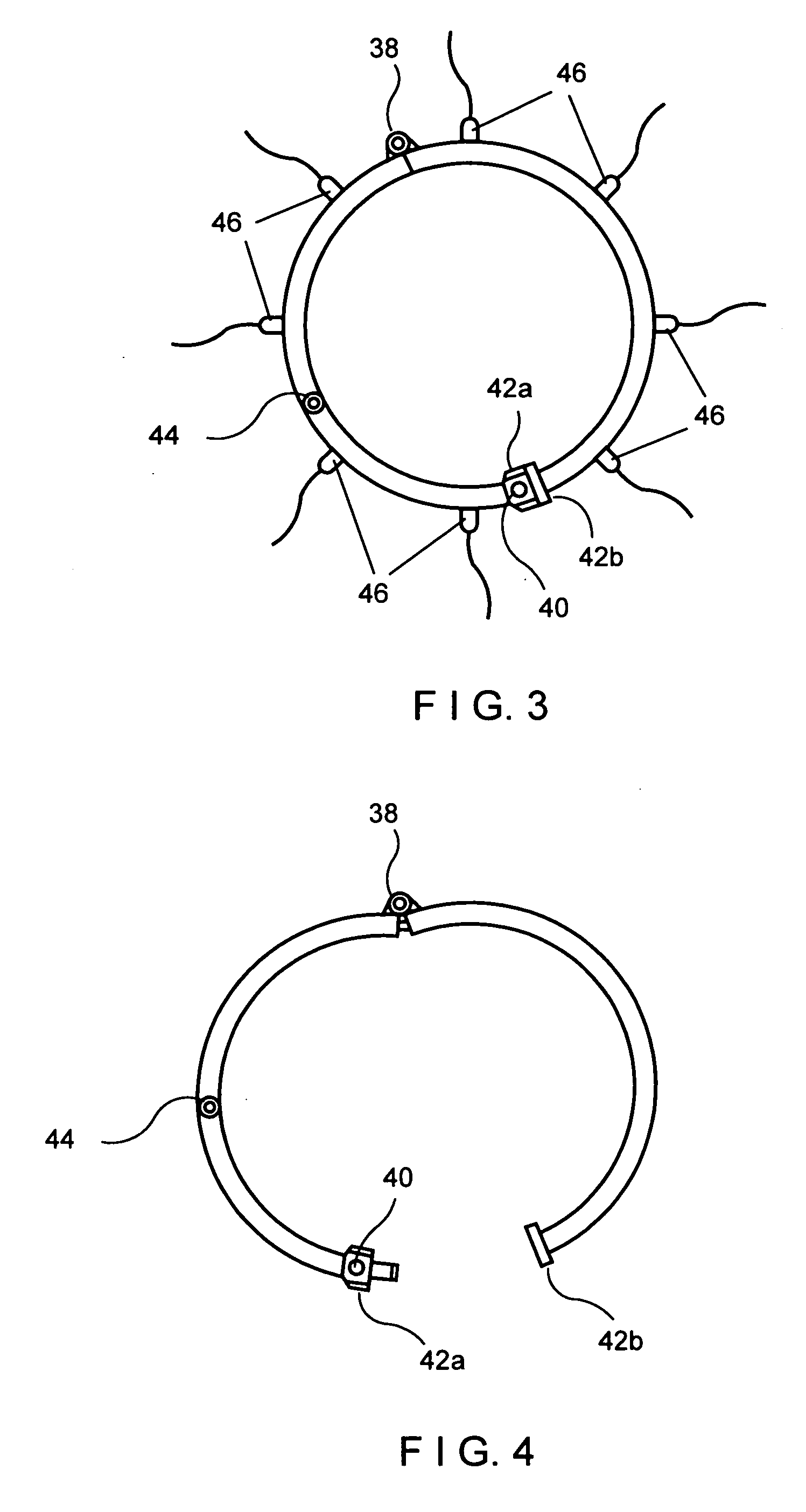
[0024] A preferred system shown in FIGS. 1 and 2 has split power rings 30, 30a and 30b in graduated sizes. The largest power ring 30 is fixed to a cord 36 for supplying electrical power to conventional electrical inlets / outlets (not shown) spaced about the power ring for receiving the power plugs of strings of lights. The other poser rings 30a and 30b are similar, except that their power-supplying cords 34 have plugs 48 for inlet / outlet connection to the rings, the plugs and complementary inlets / outlets 44 (FIGS. 3 and 4) being of a known co-axial style that is non-compatible with the other conventional electrical inlets / outlets. This limits the power rings substantially to connection to each other for some control over or suggestion of the maximum current flow through the system and / or the provision of fusing in the plugs 48, for example, for safety.

[0025] The split power rings 30, 30a, 30b each have only one substantially axial split 31, 31a, 31b. Opening of the rings to surround...


PUM


Abstract

An easily assembled interior and exterior electrification system for trees or other structural elements allows for considerable versatility of design and display options varying from simple decoration to signage and street address, for example, and easy disassembly for storage has a split ring having electrical power outlets spaced about the split ring for supplying electrical power and a cord having a connection to the split ring for supplying electrical power to the electrical power outlets.

Description

BACKGROUND OF THE INVENTION [0001] This invention relates to an extension cord system and, more particularly, a method for providing electric power in trees or indoor or outdoor structural elements, for example, to provide ornamental lighting in trees, informational material lighting under overpass constructions, or temporary lighting about building sites as may be called a power ring electrification system. [0002] The illumination of trees and other structural elements is quite common in western society, specifically during the Christmas holidays but not limited to that application. The present technique is primarily to suspend long strands of lighting end to end in series with one end attached to a current source and the other blind ending. The problems with this present technique are many and varied. They include older wiring in which the bulbs are in series and even a single blown bulb can lead to the entire strand not lighting, and great difficulty in untangling the long lighti...

Claims


Application Information

Patent Timeline
Patent Type & Authority Applications(United States)
IPC IPC(8): H05B39/00
CPCH05B39/00
Inventor BEITLER, MARTIN M.
Owner BEITLER MARTIN M
Learn More