
Auxiliary illumination for hand tools

a technology for auxiliary illumination and hand tools, which is applied in the direction of manufacturing tools, lighting and heating apparatus, and light support devices, etc. it can solve the problems of insufficient illumination in the work area, and it is difficult for an operator to do a repairing jog under the dark area, so as to improve the illumination for the user of hand tools. , the effect of convenient us

Inactive Publication Date: 2006-11-16
HIEVER
View PDF13 Cites 6 Cited by
  • Summary
  • Abstract
  • Description
  • Claims
  • Application Information

AI Technical Summary

Benefits of technology

[0005] The primary objective of the present invention is to provide an auxiliary illumination, which is easy to use and improve the illumination for the hand tools user also.

Problems solved by technology

The illumination is always not sufficient in the work area especially when we use hand tools.
It is difficult for an operator to do a repairing jog under the dark area and this is the reason why we need an auxiliary illumination to help.

Method used


Image

  • Auxiliary illumination for hand tools
  • Auxiliary illumination for hand tools
  • Auxiliary illumination for hand tools

Examples


first embodiment

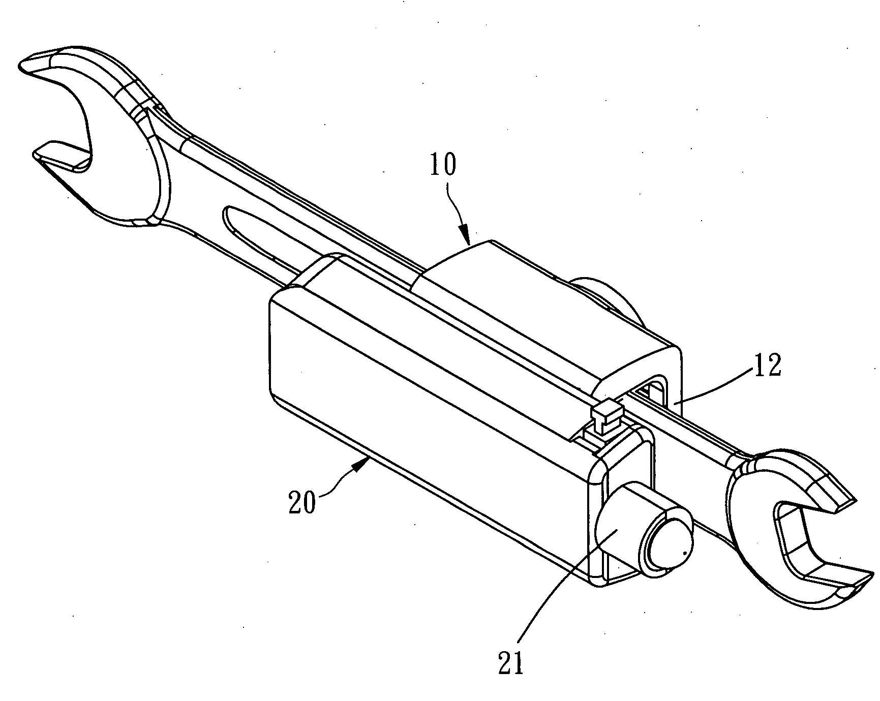
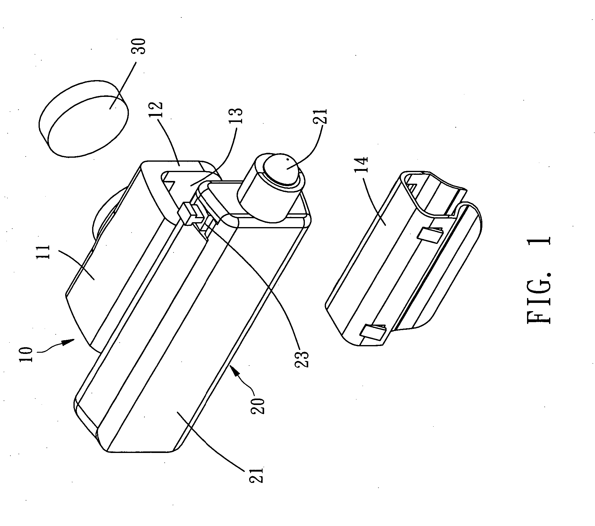
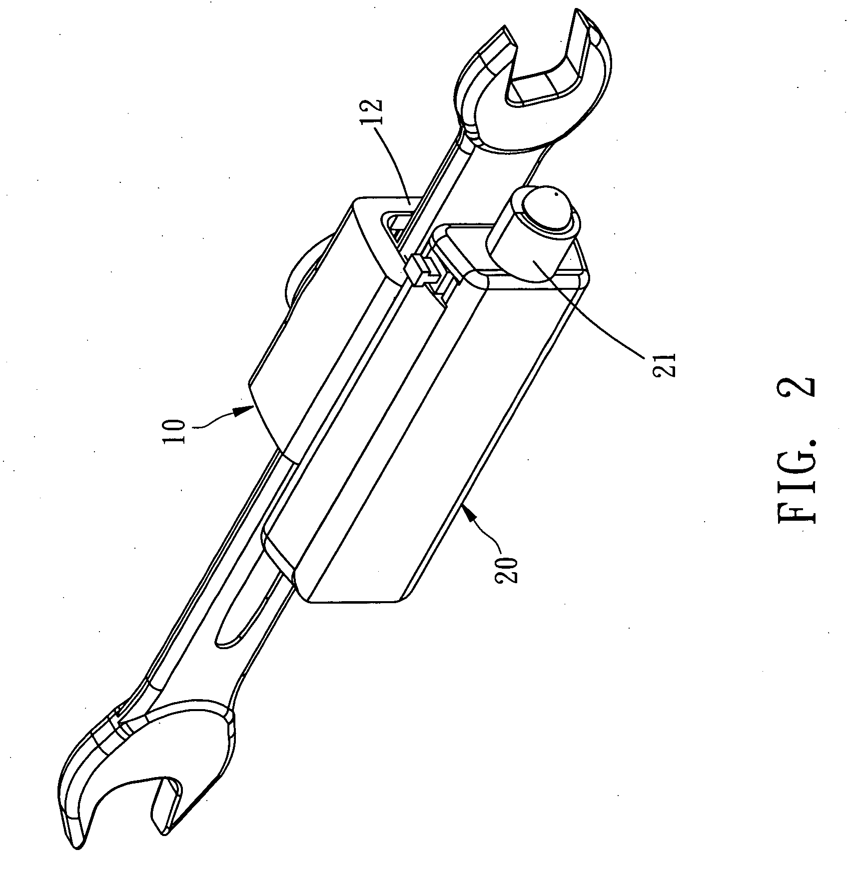
[0022] present invention can be direct clipped on a hand tool like screwdriver, socket wrench or wrench by push the hand tool into the clip area. The clip member will clip on the hand tool when the hand tool was located into the clip area as showing in FIG. 2 and FIG. 3. Owing to the illumination member pivots on the stand wall of the clip assembly, the illumination can be rotated opposite to the clip assembly easily to match the demand of the user. The way the illumination member pivots on the stand wall could be varied. The illumination can be pivoted on the clip assembly by using a single axle or a ball-and-socket joint or other similar structures.

[0023] As FIG. 5 to FIG. 7 showing, this is the second embodiment of present invention. The structures in the second embodiment are almost the same with the first embodiment. The illumination member 45 also pivots on the clip assembly. But in the second embodiment, there is no magnet on the clip assembly 40. One of the stand walls has a...

third embodiment

[0024] As showing in FIG. 8 to FIG. 10, this is present invention. There is a clip area 52 on the clip assembly 50 formed by two stand walls 51 also. There are plurality ribs locate on one side of the stand wall formed the clip member 53 in this embodiment. The illumination member 54 pivots on aside of the clip assembly also. As the above-mentioned structures, the hand tool like screwdriver can be pressed into the clip area and clipped by these ribs and opposite stand wall. As FIG. 10 showing, the clip area can add a magnet therein to enhance the stability.


PUM


Abstract

An auxiliary illumination for hand tools comprises a clip assembly for clip present invention on a hand tool has a clip area. The clip area has a clip member therein. An illumination member with a shell body pivots on the clip assembly. By the way, the illumination member can be rotated opposite to the clip assembly. One end of the illumination member has a light and a battery room inside the shell body.

Description

BACKGROUND OF THE INVENTION [0001] 1. Field of the Invention [0002] The present invention relates generally to an auxiliary illumination, and more particularly to an auxiliary illumination for hand tools. [0003] 2. Description of the Related Art [0004] We always need illumination to help when doing a repairing job. The illumination is always not sufficient in the work area especially when we use hand tools. Sometime the light will be shaded from the operator or some objects. It is difficult for an operator to do a repairing jog under the dark area and this is the reason why we need an auxiliary illumination to help. SUMMARY OF THE INVENTION [0005] The primary objective of the present invention is to provide an auxiliary illumination, which is easy to use and improve the illumination for the hand tools user also. [0006] According to the objective of the present invention, an auxiliary illumination for hand tools comprises a clip assembly having a clip area therein for clip the auxili...

Claims


Application Information

Patent Timeline
Patent Type & Authority Applications(United States)
IPC IPC(8): B25B23/18F21L4/00F21V21/08F21V33/00
CPCB25B23/18
Inventor HUANG, TONY
Owner HIEVER
Learn More