Electrical switching apparatus indicating status through panel aperture
a technology of electrical switching apparatus and panel aperture, which is applied in the direction of switching device condition indication, switch operated by excess current and arc fault, electrical apparatus, etc., can solve the problem of inability to perform operation, inability to incorporate the illuminable ring portion of the arc fault indication, and inability to operate the overload capability of the circuit breaker
- Summary
- Abstract
- Description
- Claims
- Application Information
AI Technical Summary
Benefits of technology
Problems solved by technology
Method used
Image
Examples
example 1
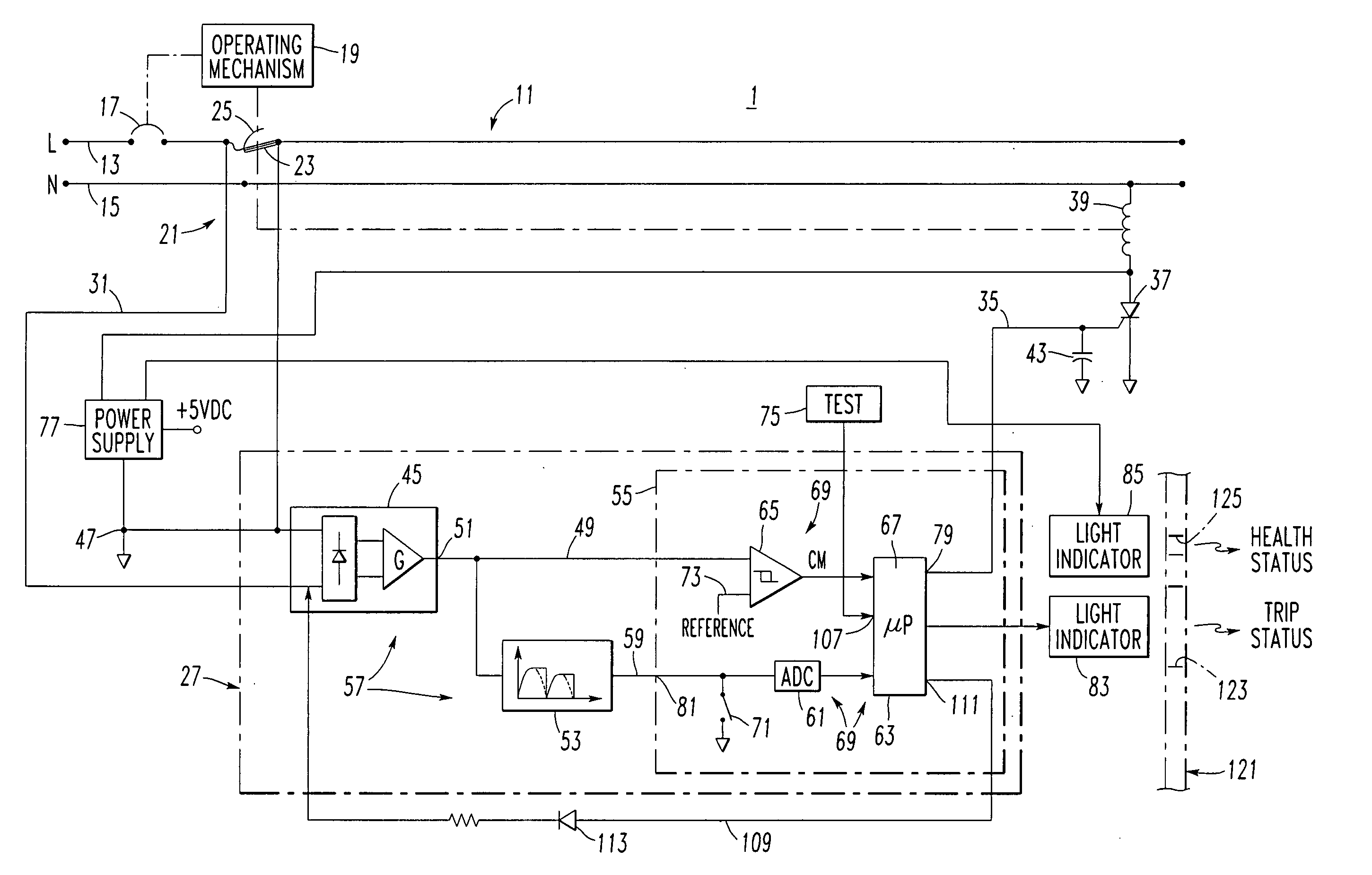
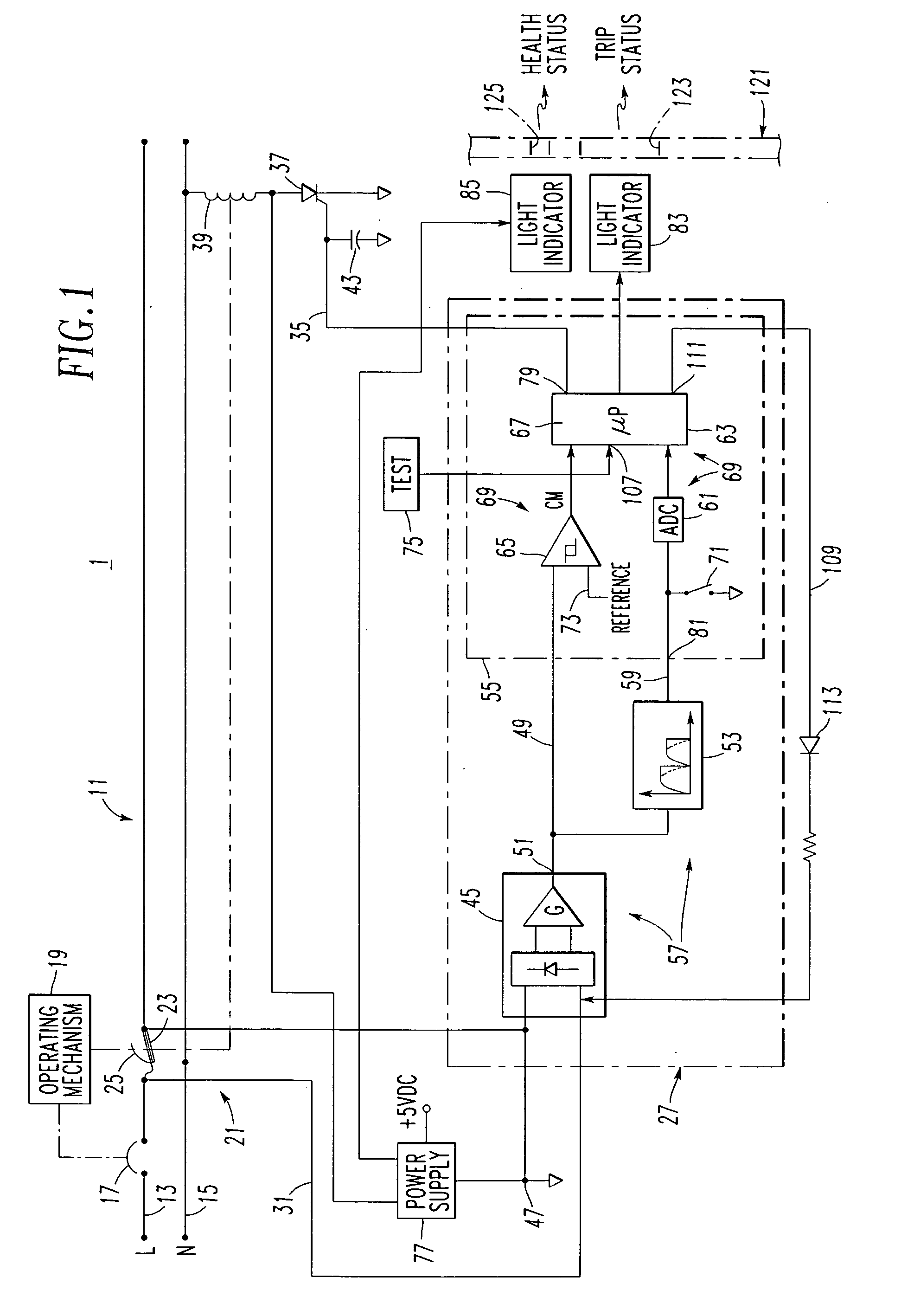
[0050] The first light indicator 83 may be an arc fault trip status LED that is illuminated in response to the detection of an arc fault and the generation of the trip signal 35 by the AFD 27 (FIG. 1).
example 2
[0051] The second light indicator 85 may be a health (e.g., functional) LED that indicates the proper function of the AFD 27 including proper powering and grounding, and that the circuit of the trip solenoid 39 is intact.
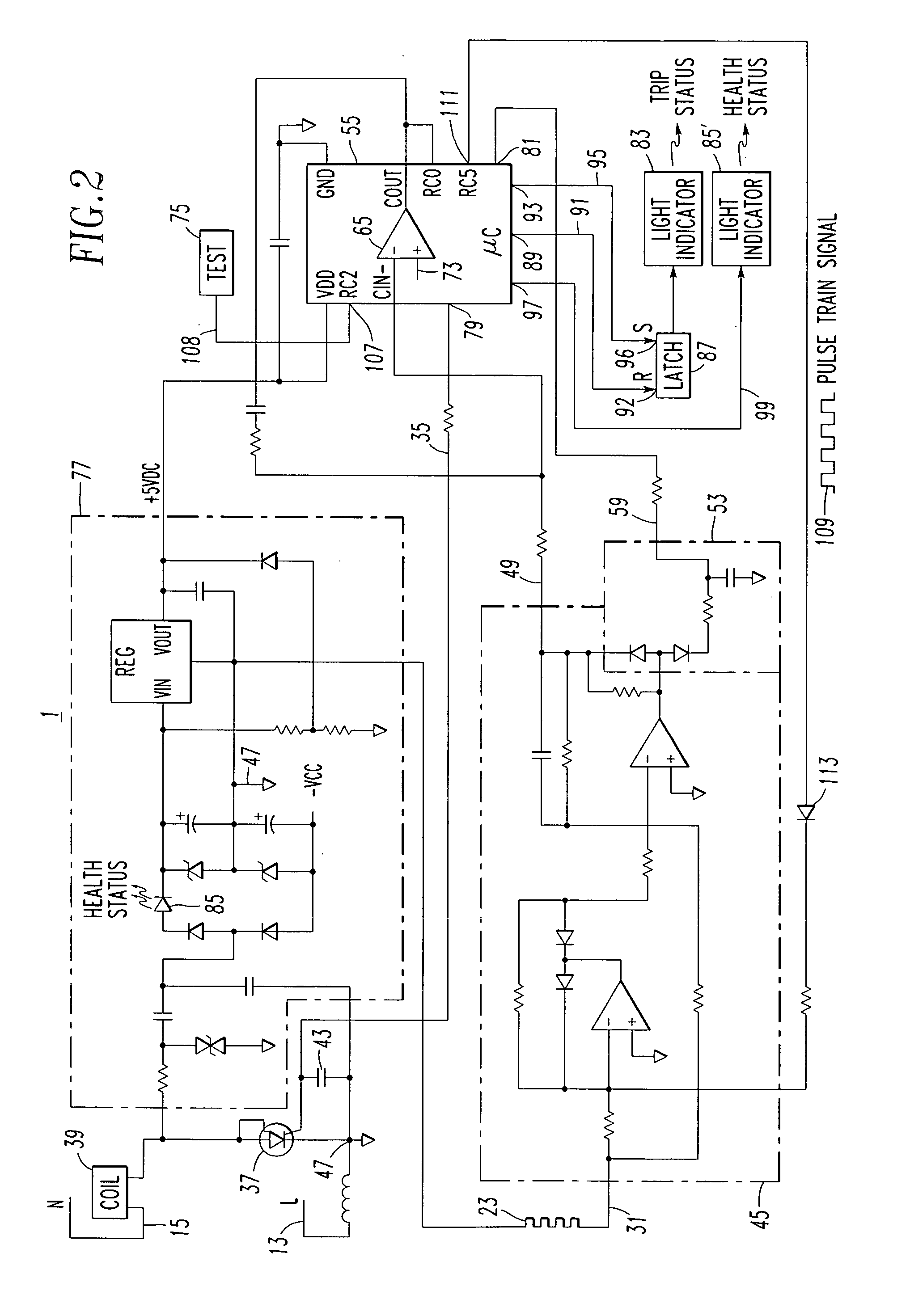
[0052] The power supply 77 generates +5 VDC for the microcontroller (μC) 55, which has the μP 63 (FIG. 1) with the digital output 97 (FIG. 2) that drives the other health LED85′ when the arc fault circuit breaker 1 is properly powered and grounded at the inputs of the power supply 77, and when the circuit of the trip solenoid 39 to the neutral 15 is intact. Alternatively, the other light indicator 85′ may indicate that both of the μP 63 and the power supply 77 are functional. The light indicator 85′ may be used in addition to or instead of the light indicator 85.
[0053] Continuing to refer to FIG. 2, another digital input RC2107 of μC 55 is employed to input a test signal 108 from the test circuit 75. A further digital output RC5111 of μC 55 includes a suitable pul...
example 3
[0055]FIG. 3 shows a conventional aircraft or aerospace panel 121 (shown in phantom line drawing) including two different apertures, such as through holes 123,125, for mounting of a circuit breaker 127. The circuit breaker 127, which may be the same as or similar to the circuit breaker 1 of FIGS. 1 and 2, includes one or more light indicators 129 (only one light indicator 129 is shown in FIG. 3) through one or both of the holes 123,125 (the light indicator 129 is through the hole 125 of FIG. 3).
[0056] The circuit breaker 127 includes a housing 131 adapted to be coupled to the panel 121, which is disposed between a bezel 133 and a nut 135 as is conventional. The circuit breaker 127 also includes an operating mechanism 137 having a push-pull operating handle 139 adapted to pass through the first hole 123 of the panel 121. In accordance with an important aspect of the invention, the light indicator 129 is disposed through the second hole 125 of the panel 121 to indicate a status (e.g....
PUM
 Abstract
Description
Claims
Application Information
 - R&D
- Intellectual Property
- Life Sciences
- Materials
- Tech Scout
- Unparalleled Data Quality
- Higher Quality Content
- 60% Fewer Hallucinations
Browse by: Latest US Patents, China's latest patents, Technical Efficacy Thesaurus, Application Domain, Technology Topic, Popular Technical Reports.
© 2025 PatSnap. All rights reserved.Legal|Privacy policy|Modern Slavery Act Transparency Statement|Sitemap|About US| Contact US: help@patsnap.com


