
Temperature regulation device for a fluid-containing receptacle and use thereof

a technology of temperature regulation device and fluid-containing receptacle, which is applied in the direction of domestic cooling apparatus, refrigerating machines, machines using electric/magnetic effects, etc., can solve the problems of messy system of ice with refuse containers, significant disadvantages of conventional approaches to cooling beer kegs,

Inactive Publication Date: 2006-11-09
HUNNELL ADAM
View PDF13 Cites 66 Cited by
  • Summary
  • Abstract
  • Description
  • Claims
  • Application Information

AI Technical Summary

Benefits of technology

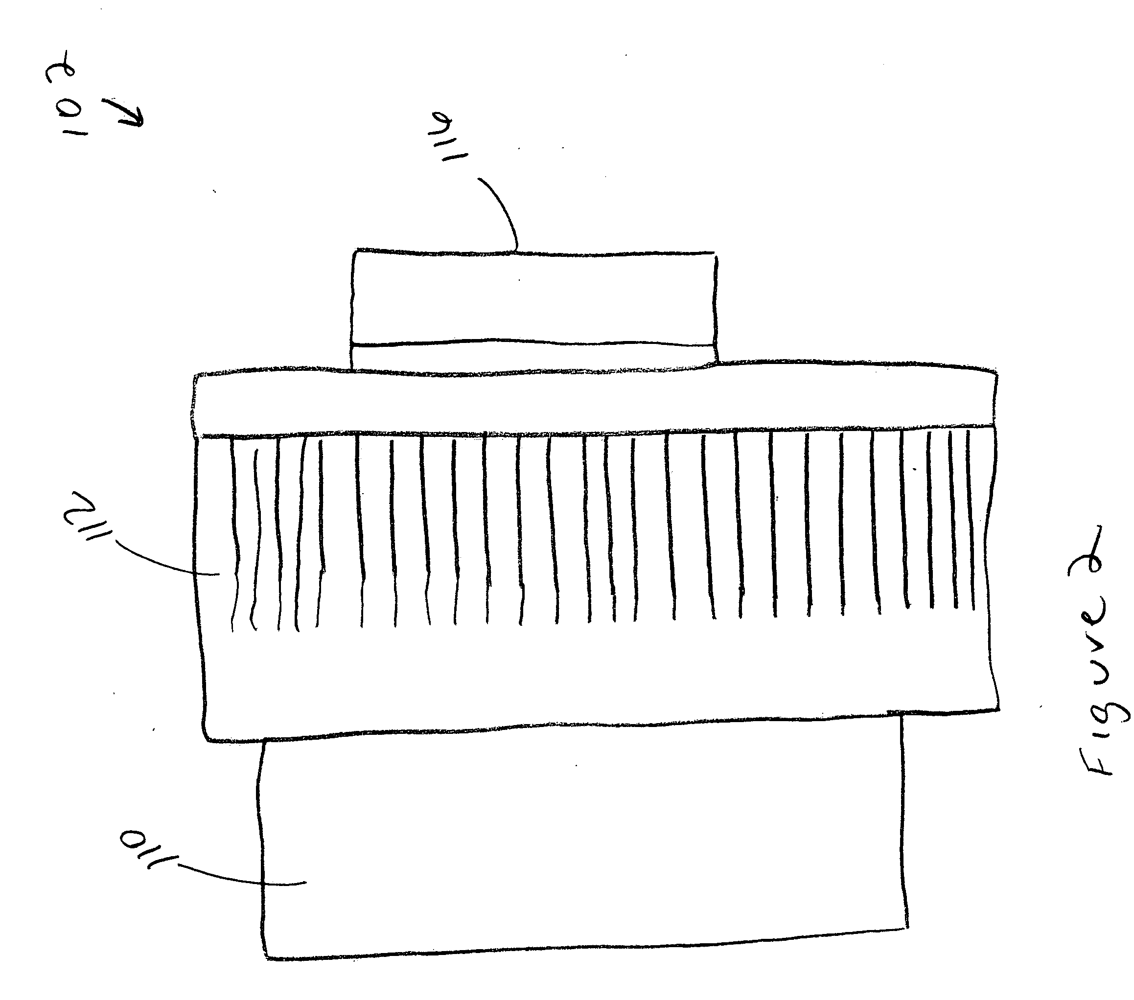
[0005] In accordance with another example aspect, the present invention is also directed to a temperature regulation device adapted for coupling with a fluid-containing receptacle and for maintaining the fluid thereof at a desired temperature state. The device generally includes a thermoelectric module comprising a cooling surface and a heating surface, and wherein the cooling surface is adapted to be disposed in proximity to a surface of the receptacle; and an insulation means, associated with the thermoelectric module, for insulating the receptacle against heat loss.

Problems solved by technology

As known, conventional approaches for cooling a beer keg suffer from significant disadvantages.
By way of another example, the system of employing ice with a refuse container is often a messy endeavor, as water and ice are easily diverted from the container, especially as motor functions become impaired.

Method used


Image

  • Temperature regulation device for a fluid-containing receptacle and use thereof
  • Temperature regulation device for a fluid-containing receptacle and use thereof
  • Temperature regulation device for a fluid-containing receptacle and use thereof

Examples


example 1

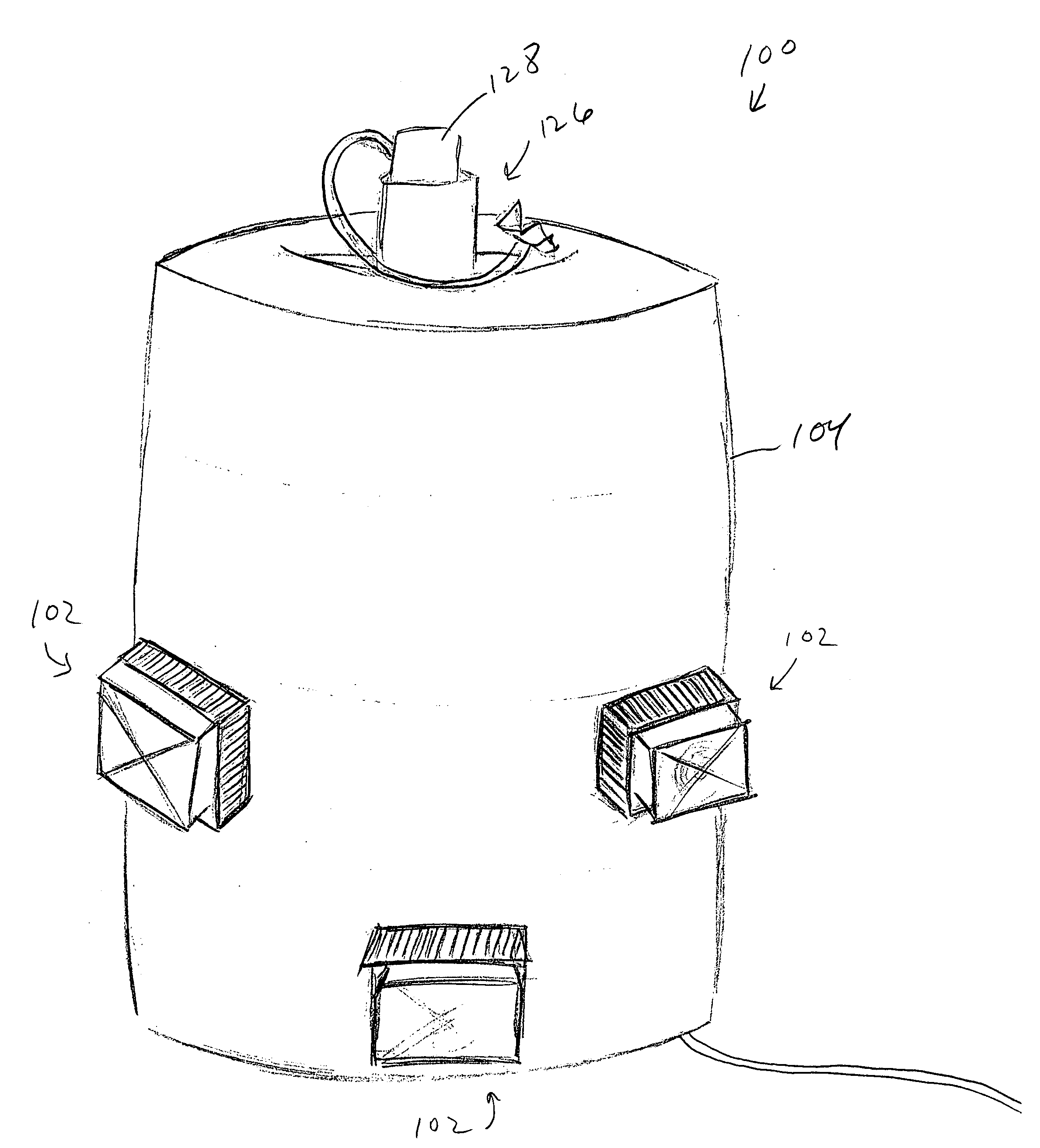
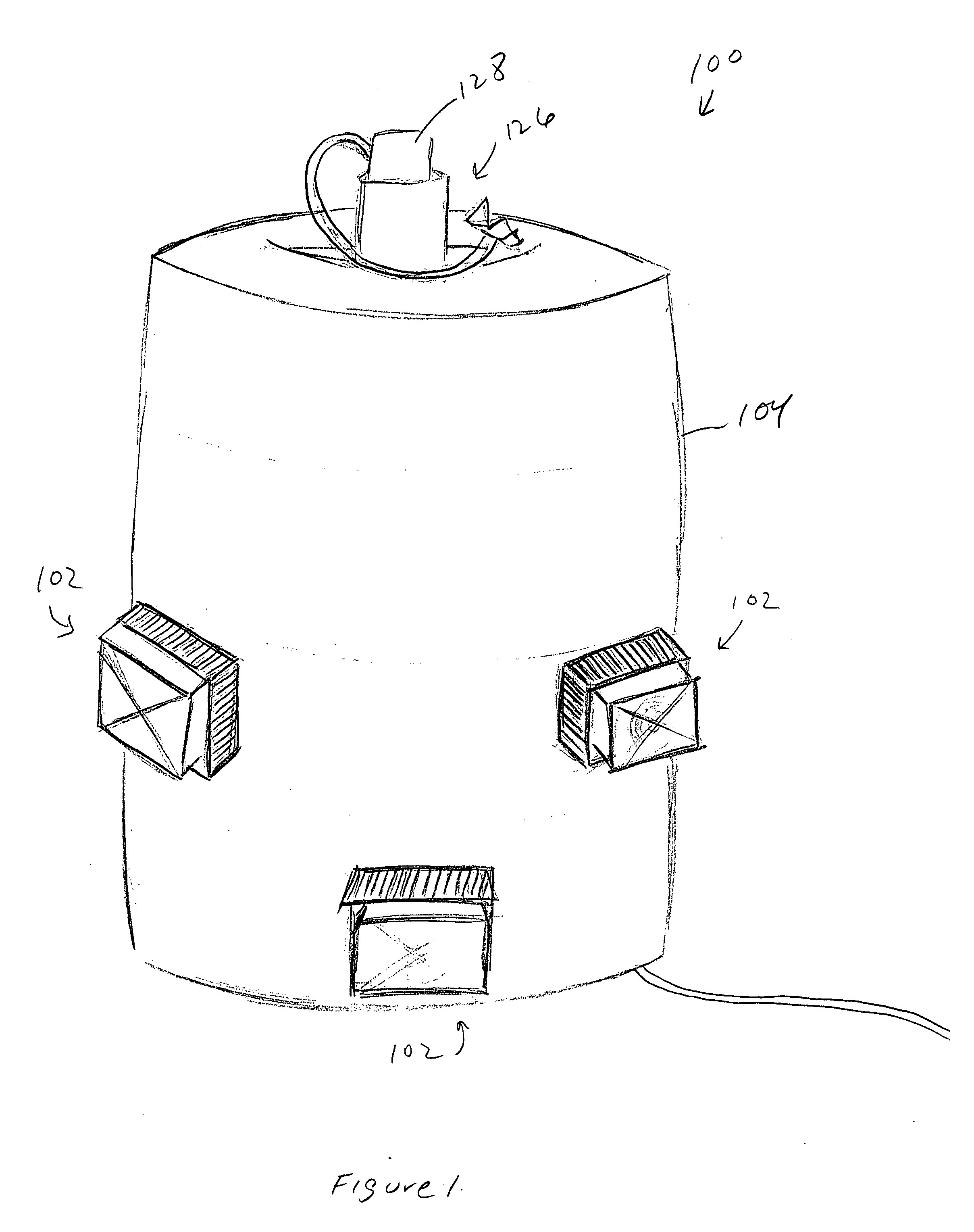
[0027] Table 1 illustrates the results of an experiment performed to compare the amount of heat loss generated by a receptacle, in this case, a keg, alone, and the amount of heat loss generated by the keg associated with the insulation means 104 of the present invention, but significantly not including the temperature regulation means 102. For each measurement, one to two quarts of beer were poured; the first half was poured and not measured to get the beer that was left in the tap out of the tap and the second half was then poured and used to measure the temperature of the beer. The results of the study indicate that the insulation means 104 alone significantly delays the onset of significant temperature increases in the fluid maintained in the keg.

TABLE 1Keg with InsulationKeg AloneTemperatureMinutesHoursTemperature (F.)MinutesHours(F.)00.0035.500.0032.5150.2538200.3332.6400.6740.6350.5832.7651.0842.3601.0033851.4243.1751.2533.61101.8344.1971.6234.31252.0844.31151.9235.11502.504...

example 2

[0028] Table 2 illustrates the results of an experiment performed to understand the amount of heat loss generated by a receptacle 106 having the temperature regulation device 100 of the present invention associated therewith. Additionally, the device 100 in this embodiment was modified to include spacers 114. The results of the study indicate that the device 100 was able to maintain beer at a cool temperature (e.g., below 42 F) for a considerable period of time, at least that commensurate with a typical party. Specifically, the test was performed over a period of 75 hours and the temperature was maintained below 42 F for over 46 hours.

TABLE 2Device using SpacersTested over a 76 Hour PeriodMinutesHoursTemperature (F.)Measured on . . .00392nd cup from keg450.7541.82nd cup from keg2253.75412nd cup from keg2554.25412nd cup from keg3455.7541.22nd cup from keg76512.7542.52nd cup from keg91515.2541.22nd cup from keg121520.2541.42nd cup from keg153025.541.82nd cup from keg171028.540.8star...


PUM


Abstract

A temperature regulation device for a fluid-containing receptacle and use thereof. The device preferably includes a temperature regulation means for maintaining the fluidic contents of the receptacle at a desired temperature (e.g., a relatively lower temperature, a relatively higher temperature, etc.) and an insulation means for retarding heat loss from the receptacle. In a preferred embodiment, the temperature regulation means is provided as a thermoelectric module.

Description

FIELD OF THE INVENTION [0001] The present invention is directed to a temperature regulation device. More particularly, the present invention is directed to a temperature regulation device particularly adapted for maintaining the fluidic contents of a receptacle, such as a conventional beer keg, at a desired, especially cooled, temperature. BRIEF DISCUSSION OF THE RELATED ART [0002] A plurality of receptacles are conventionally used for housing a fluid. Of particular relevance to the present invention are receptacles commonly employed for drinking beverages (e.g., beer, wine, soda, water, and the like). Common receptacles are beer kegs, wine boxes, wine bottles, coolers, and the like, especially those having an integral dispensing mechanism. Such receptacles are often used in connection with a social gathering, such as a party, and it is often desirable to maintain the fluidic contents thereof at a reduced temperature state for increased enjoyment in consumption. Typical approaches f...

Claims


Application Information

Patent Timeline
IPC IPC(8): F25B21/02
CPCF25B21/02F25B2321/023F25D2331/802F25D31/006F25B2321/0251
Inventor HUNNELL, ADAM
Owner HUNNELL ADAM
Learn More