Electric power supply device of a tape-end detecting sensor for a tape recorder

a technology of detecting sensor and tape recorder, which is applied in the field of electric power supply device of tape-end detecting sensor for tape recorder, can solve the problems of increasing manufacturing cost and increasing the number of manufacturing processes, and achieve the effect of less expensive and simpler manner

Inactive Publication Date: 2006-11-02
SAMSUNG ELECTRONICS CO LTD
View PDF9 Cites 0 Cited by
  • Summary
  • Abstract
  • Description
  • Claims
  • Application Information

AI Technical Summary

Benefits of technology

[0013] The present invention has been developed in order to solve the above drawback and other problems associated with the conventional arrangement. An aspect of the present invention is to provide a power supply device of a tape-end detecting sensor for a tape recorder having an improved construction capable of supplying a power to the tape-end detecting sensor in a less expensive and simpler manner.

Problems solved by technology

However, the conventional tape recorder having the above-described construction has drawbacks such as increased manufacturing cost and an increased number of manufacturing processes due to the presence of the extra resilient pressing member 195.

Method used


Image

  • Electric power supply device of a tape-end detecting sensor for a tape recorder
  • Electric power supply device of a tape-end detecting sensor for a tape recorder
  • Electric power supply device of a tape-end detecting sensor for a tape recorder

Examples


Embodiment Construction

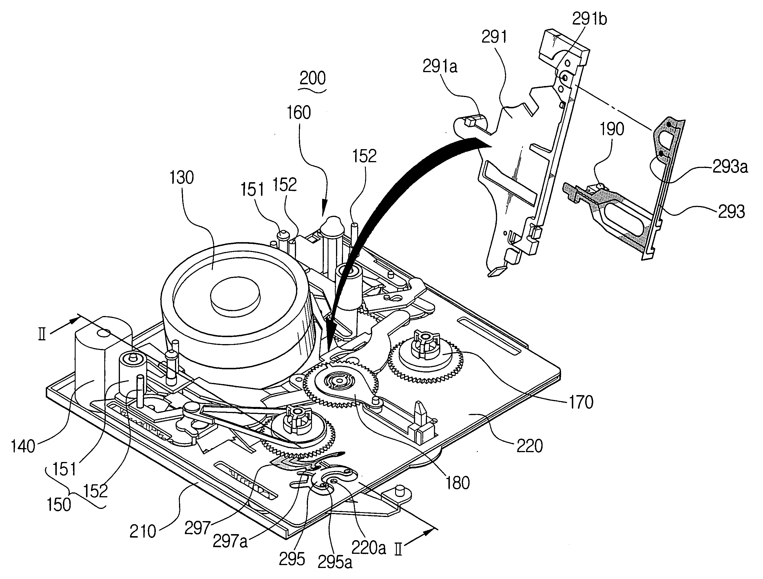
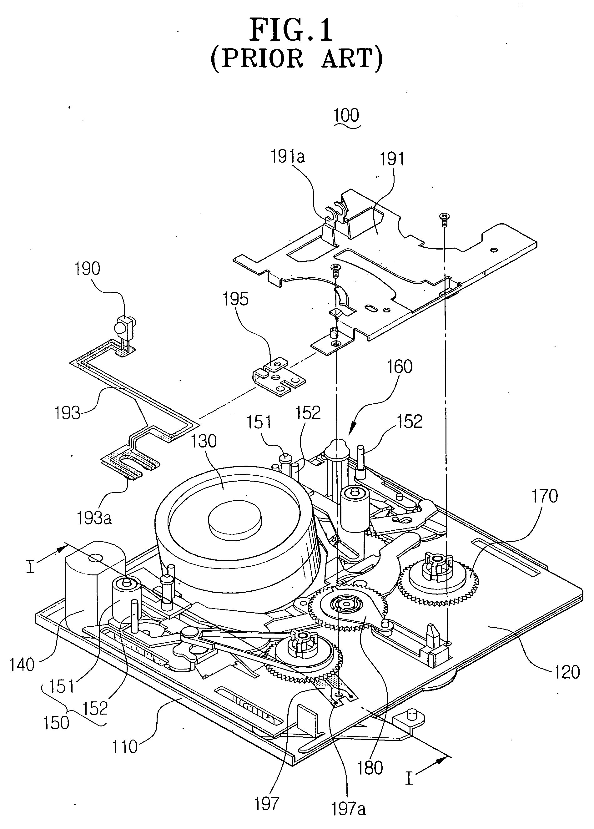
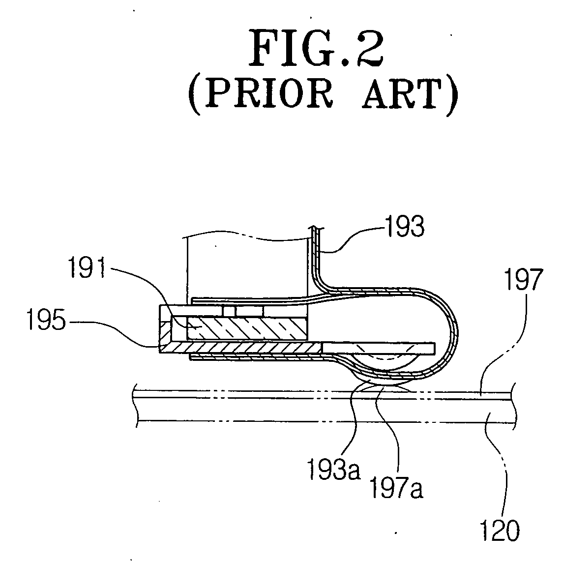
[0023] Certain embodiments of the present invention will be described in greater detail with reference to the accompanying drawings. With respect to elements identical to those of the conventional tape recorder shown in FIGS. 1 and 2, like reference numerals are assigned, and a detailed description of those components is omitted for conciseness.

[0024] Referring to FIGS. 3 and 4, a tape recorder according to an embodiment of the present invention employs a moving deck 200 including a main-chassis 210 and a sub-chassis 220. A power supply device of a tape-end detecting sensor includes a reel cover 291, a first power transmitting member 293, a second power transmitting member 297, and a resilient pressing member 295.

[0025] The reel cover 291 is disposed on the sub-chassis 220 to cover a reel table 170 and an idler assembly 180, and has a seating portion 291A formed on an upper surface thereof. In this embodiment, a light-emitting element 190 is seated on the seating portion 291A. How...


PUM

PropertyMeasurementUnit
contacting forceaaaaaaaaaa
magneticaaaaaaaaaa
transparentaaaaaaaaaa

Abstract

A power supply device of a tape-end detecting sensor for a tape recorder. The power supply device comprises a reel cover disposed on a sub-chassis, with a tape-end detecting sensor being seated on the reel cover for detecting the passing of a terminal end of a magnetic portion of a magnetic tape, a first power transmitting member mounted in the reel cover to be connected to the detecting sensor and having a first contacting portion, and a second power transmitting member disposed on the sub-chassis and having a second contacting portion that comes into contact with the first contacting portion when the reel cover is mounted on the sub-chassis. The power supply device further comprises a resilient pressing member integrally formed with the sub-chassis, for resiliently pressing the second contacting portion toward the first contacting portion to improve a contacting force between the first and the second contacting portions. Accordingly, the contacting force between the first and the second contacting portions can be improved without employing a separate resilient pressing member and thus, the number of manufacturing process and the manufacturing cost can be decreased.

Description

[0001] This application is a division of U.S. patent application Ser. No. 10 / 446,862, filed May 29, 2003, which claims benefit under 35 U.S.C. §119 from Korean Patent Application No. 2002-55817, filed on Sep. 13, 2002, the entire content of which is incorporated herein by reference.BACKGROUND OF THE INVENTION [0002] 1. Field of the Invention [0003] The present invention relates to a tape recorder, and more particularly, to a power supply device that supplies power for a tape recorder to a tape-end detecting sensor capable of detecting the passing of a magnetic portion of a magnetic tape. [0004] 2. Description of the Related Art [0005] A tape recorder having a deck mechanism, such as a video tape recorder (VTR), a digital audio tape (DAT), and a camcorder, is an apparatus that records and reproduces audio and video information from a magnetic tape running along a predetermined path. [0006]FIG. 1 shows an example of the interior of a camcorder employing a moving deck 100. As shown in ...

Claims


Application Information

Patent Timeline
Patent Type & Authority Applications(United States)
IPC IPC(8): G11B5/008G11B33/12G11B15/06G11B15/08G11B25/06G11B33/02
CPCG11B15/08Y10T29/49002G11B33/02G11B25/063G11B15/06
Inventor KIM, BONG-JOOCHOI, DO-YOUNGSEO, JAE-KAB
Owner SAMSUNG ELECTRONICS CO LTD
Why Eureka
Try Eureka