
Flexible displays as an input device

a display device and flexible technology, applied in computing, instruments, electric digital data processing, etc., can solve the problems of limiting the amount of surface space, limiting the size or number of control elements, and limiting the space of mobile devices

Inactive Publication Date: 2006-10-26
IBM CORP
View PDF3 Cites 305 Cited by
  • Summary
  • Abstract
  • Description
  • Claims
  • Application Information

AI Technical Summary

Benefits of technology

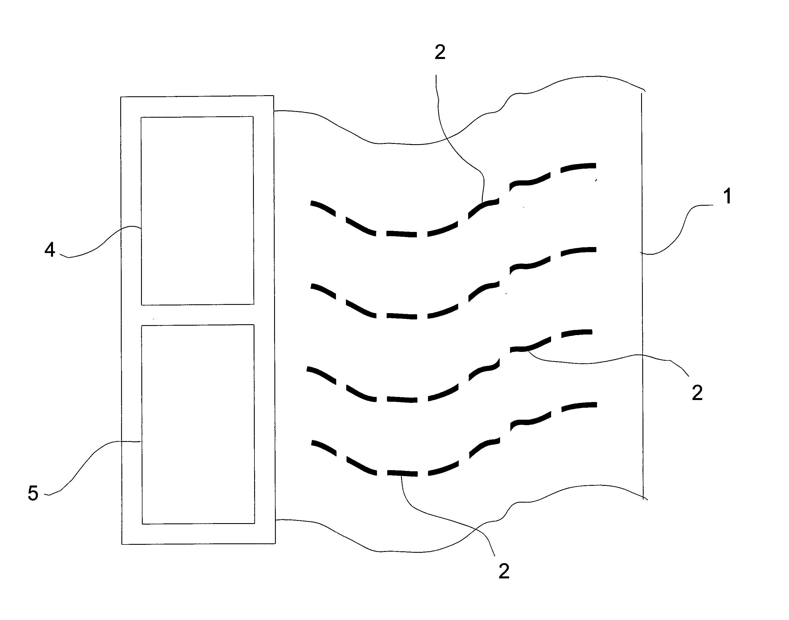
The invention is a display that can bend and show different images. It has bend sensors that measure the bends in the display surface. The display can detect the position and orientation of the bends and use this information to control the display. For example, a scroll bar or cursor can be controlled by the position and orientation of the bend. The method involves creating position and orientation measurements for the bends and mapping them to a controller function to control the display. The technical effect of this invention is to provide a flexible display that can show different images and be controlled by the user's bends.

Problems solved by technology

Mobile devices typically have limited space and small screens.
In order to provide a larger screen size, a device designer is often required to further limit the size or number of control elements simply because the smaller sizes that have permitted mobile devices to be mobile, also tend to restrict the amount of surface space that can be used for display or control.
It is envisioned that unrolling or unfolding flexible displays may reduce the requirement for small or light devices to necessarily have small displays, but device output is only one part of the user-interface problem.
However, the size of such external input mechanisms can minimize the advantage provided by the size of the easily carried compact device.
This latter approach potentially address the issue of device size, but adds a usage constraint, requiring the availability of a large flat surface.
an). However, the simple modes of direct manipulation mentioned above all have drawb
acks. The single-sensor flexible display lacks the ability to detect the richness of the user interaction with the display because it is only capable of measuring one kind of
bend. Similarly, touchscreen displays typically do not detect the richness of the user interaction (instead capturing only a location expressed in X and Y coordi
nates). Where a tablet and stylus is used in combination to achieve greater levels of control, the stylus becomes yet another component which can be misplaced or

Method used


Image

  • Flexible displays as an input device
  • Flexible displays as an input device
  • Flexible displays as an input device

Examples


Embodiment Construction

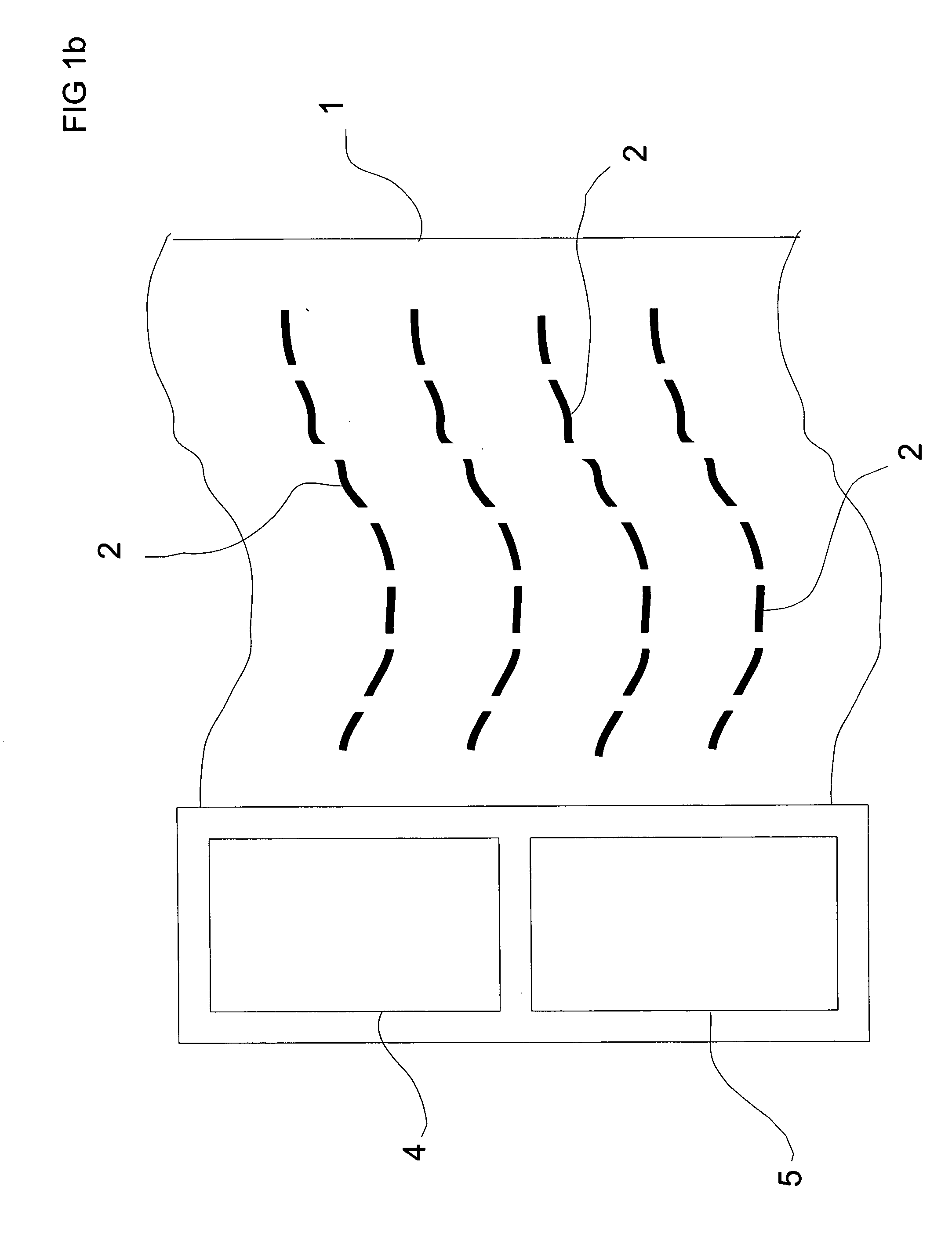
[0029] As will be understood the present application discloses the use of a flexible display as an input device. An exemplary display may be constructed by providing sensors to measure the amount of bend found exhibited by a display composed of electronic ink or organic light emitting diodes. Strain gauges can be used to detect bends in the display. Different types of bend sensors may even be used in combination if so desired. In one embodiment, the bend of the display can be measured by peizo-electric bimorphs, which can increase or decrease voltage depending on the degree of bend. Because only the sensors longitudinally perpendicular to the line of bend will change values, an array of peizo-electric bimorphs strategically distributed within the flexible surface of the display will indicate where the bend is located and how the bend is oriented.

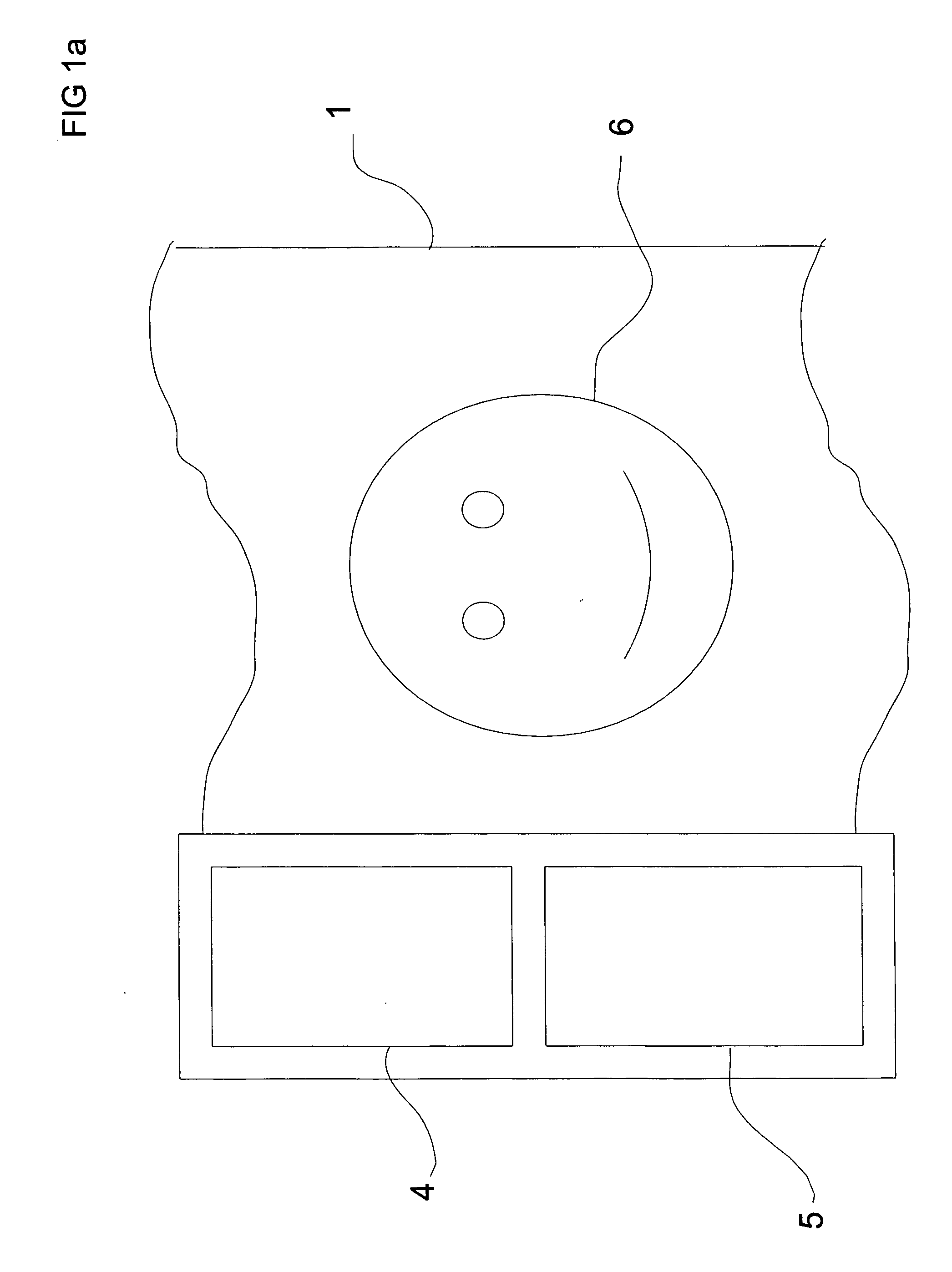
[0030]FIG. 1a shows one display according to the current invention. The display shown has a flexible surface 1 which exhibits the image of...


PUM


Abstract

A display comprising: (a) a flexible surface operable to exhibit images, the aforesaid flexible surface being capable of exhibiting variable degrees of bend; (b) a plurality of bend sensors for creating a plurality of bend measurements from a line of bend; and (c) a line detection device operable to detect orientation and position of the aforesaid line of bend based on the aforesaid plurality of bend measurements.

Description

FIELD OF THE INVENTION [0001] The present invention relates to input and display devices for computer systems. BACKGROUND OF THE INVENTION [0002] Mobile devices typically have limited space and small screens. They have room for only a few buttons. In order to provide a larger screen size, a device designer is often required to further limit the size or number of control elements simply because the smaller sizes that have permitted mobile devices to be mobile, also tend to restrict the amount of surface space that can be used for display or control. Advances in display technology have made it feasible to construct displays that can be flexed to conform to non-planar surfaces or folded to facilitate more compact storage. At present, OLED displays are being prototyped on flexible substrates by Universal Displays, University of Arizona Optical Sciences Center, Philips Research, Dupont, Army Research Labs, other members of the US Display Consortium, etc. It is envisioned that unrolling o...

Claims


Application Information

Patent Timeline
Patent Type & Authority Applications(United States)
IPC IPC(8): G09G5/00
CPCG06F3/002G09G2380/02G06F3/011G09G3/20G09G3/035
Inventor NARAYANASWAMI, CHANDRASEKHARRAQHUNATH, MANDAYAM THONDANUR
Owner IBM CORP
Learn More