Pedal/cleat assembly
a technology of clamping and pedals, applied in the field of pedals, can solve the problems of difficult adjustment, unsatisfactory provisions for adjusting the float range, etc., and achieve the effect of preventing relative rotation
- Summary
- Abstract
- Description
- Claims
- Application Information
AI Technical Summary
Benefits of technology
Problems solved by technology
Method used
Image
Examples
first embodiment
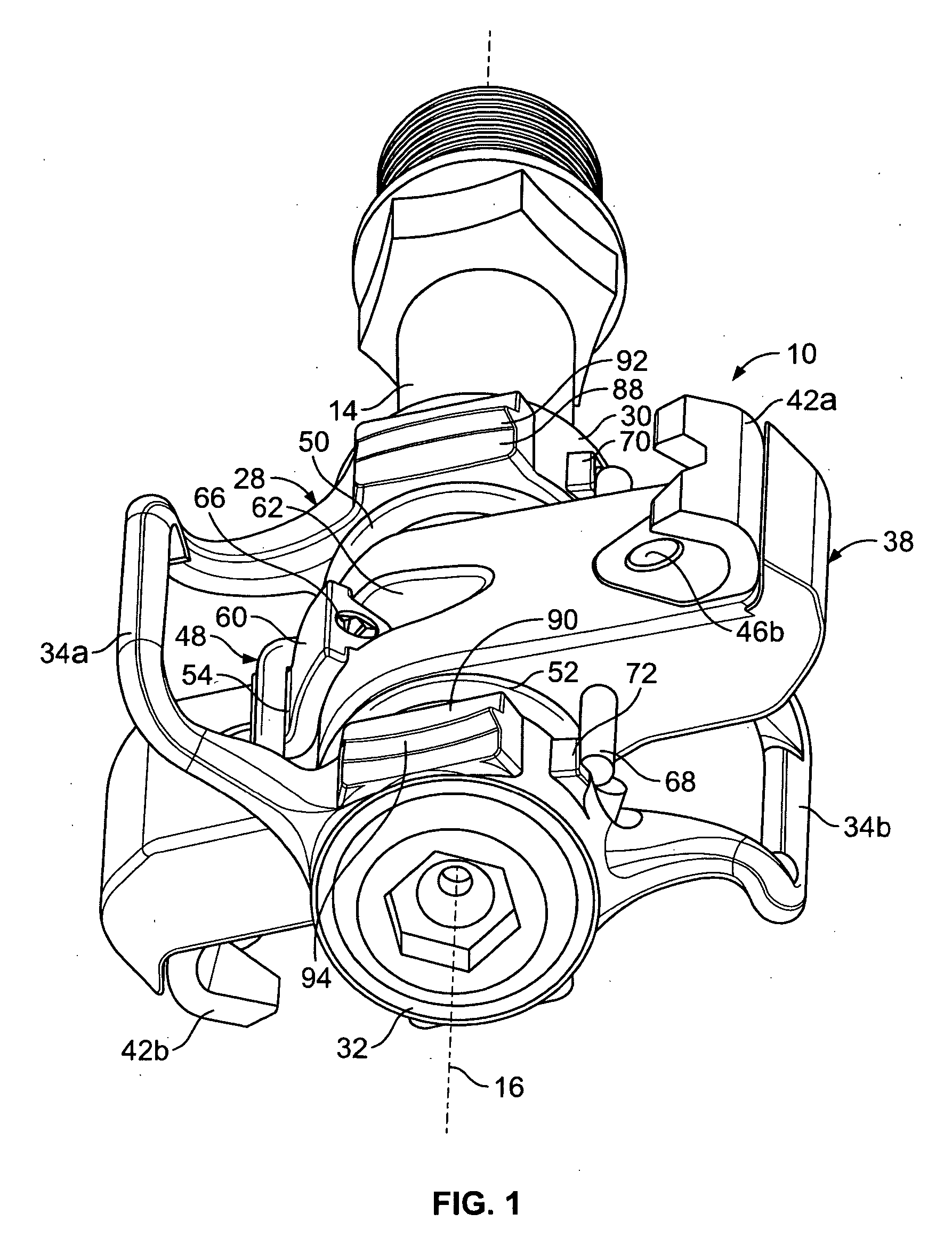
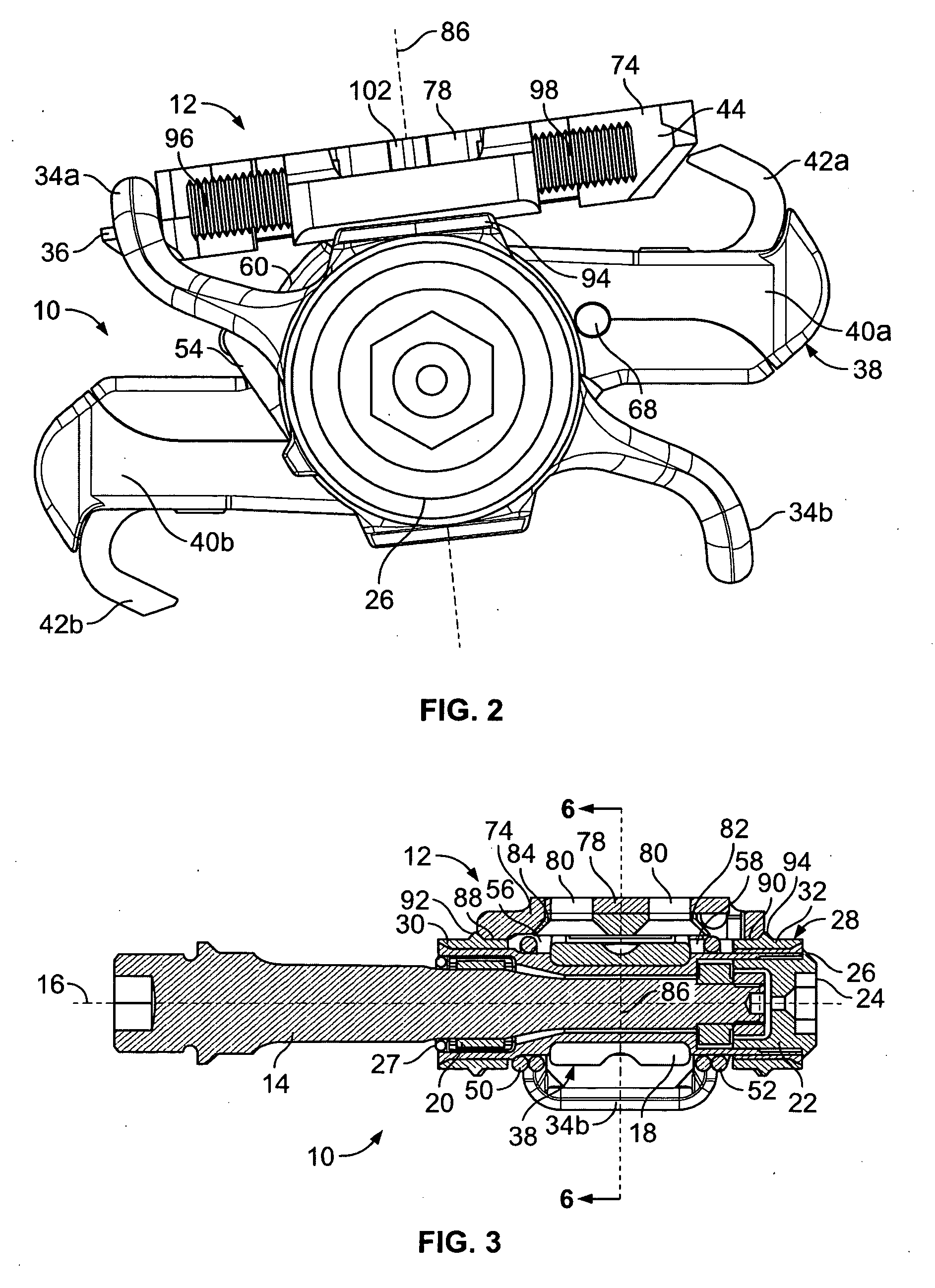
[0023] With reference now to the illustrative drawings, and particularly to FIGS. 1-4 and 6, there is shown a bicycle pedal / cleat assembly in accordance with the invention, including a pedal assembly 10 and an associated cleat assembly 12. The cleat assembly is secured to the underside of the sole of a rider's shoe (not shown), and it is configured to be attachable to the pedal assembly in a manner that allows limited rotational movement, but to be released from that attachment if the rotational movement exceeds a selected angular amount. Only a left-side pedal assembly is shown in the drawings and discussed below, although it will be understood that a similar, mirror-image pedal assembly can be located on the bicycle's right side.
[0024] More particularly, the pedal assembly 10 includes an elongated spindle 14 that projects laterally from a bicycle crank (not shown). The spindle is rotatable about a spindle axis 16 oriented to be parallel with the crank's rotation axis. A bearing sl...
second embodiment
[0038]FIGS. 7-9 depicts a cleat assembly 104 in accordance with the invention, suitable for use with the pedal assembly 10 of FIGS. 1-6. The cleat assembly 104 includes a first disc-shaped cleat body 106 defining a forward projection 108 and a rearward projection 110, for engagement with, and retention by, the respective forward and rearward cleat retainers 34 and 42 of the pedal assembly. The cleat assembly further defines a second disc-shaped cleat body 112 having two circular openings 114a, 114b for receiving attachment screws (not shown) that can be used to attach the body to the underside of the sole of a rider's shoe (not shown). The second cleat body 112 is configured to be secured to the first cleat body 106, for limited rotation about a cleat rotation axis. Access to the attachment screws that attach the first cleat body 106 to the rider's shoe is provided by enlarged openings 118a, 118b (FIG. 8) formed in the second cleat body 112.
[0039] More particularly, the first disc-s...
third embodiment
[0042]FIGS. 10 and 11 depict a cleat assembly 138 in accordance with the invention, suitable for use with the pedal assembly 10 of FIGS. 1-6. The cleat assembly 138 includes a main cleat body 140 that defines a forward projection 142 and a rearward projection 144, configured for engagement with, and retention by, the respective forward cleat retainer 34 and rearward cleat retainer 42 of the pedal assembly. The main cleat body 140 also defines an open interior configured to receive an elongated insert 146 in an orientation generally transverse to a longitudinal axis defined by the forward and rearward projections. The insert includes three lobes: a central lobe 148 formed in the shape of a disc having two arcuate sidewalls 150a and 150b, and the insert further includes two end lobes 152a, 152b located on opposite sides of the central lobe. The main cleat body 140 includes a rib 154 extending longitudinally across its open interior, for supporting the insert 146. The rib defines arcua...
PUM
 Abstract
Description
Claims
Application Information
 - R&D Engineer
- R&D Manager
- IP Professional
- Industry Leading Data Capabilities
- Powerful AI technology
- Patent DNA Extraction
Browse by: Latest US Patents, China's latest patents, Technical Efficacy Thesaurus, Application Domain, Technology Topic, Popular Technical Reports.
© 2024 PatSnap. All rights reserved.Legal|Privacy policy|Modern Slavery Act Transparency Statement|Sitemap|About US| Contact US: help@patsnap.com


