
Mechanism for tilting retractable needle

a retractable needle and mechanism technology, which is applied in the direction of intravenous devices, infusion needles, infusion devices, etc., can solve the problems of unresilient plastic end surfaces of rigid plastic materials, unreliable pistons of all commercial syringes, and high risk of stabbing for operators

Inactive Publication Date: 2006-10-12
INTAI TECH CORP
View PDF1 Cites 12 Cited by
  • Summary
  • Abstract
  • Description
  • Claims
  • Application Information

AI Technical Summary

Benefits of technology

[0009] An object of the present invention is to provide a mechanism for tilting a retractable needle, which enable the needle to tilt during retracting the needle back into the barrel.

Problems solved by technology

However, such behavior has a lot of risk of stabbing for the operator.
As a result, engagement between the hook and the connector becomes impossible.
However, the pistons of all commercial syringes have unresilient end surfaces made from rigid plastic material.
That is, the above retractable mechanism is infeasible.

Method used


Image

  • Mechanism for tilting retractable needle
  • Mechanism for tilting retractable needle
  • Mechanism for tilting retractable needle

Examples


first embodiment

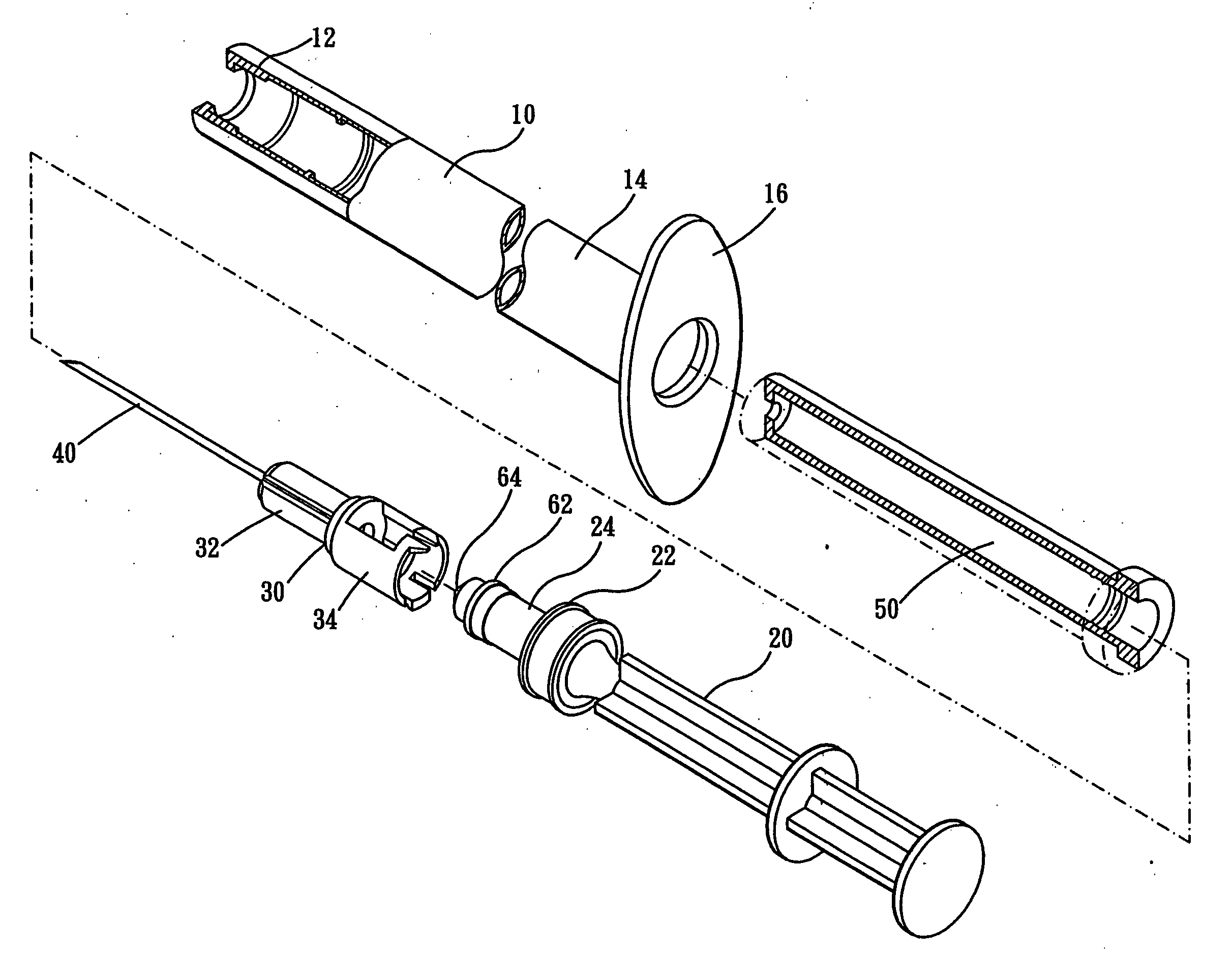
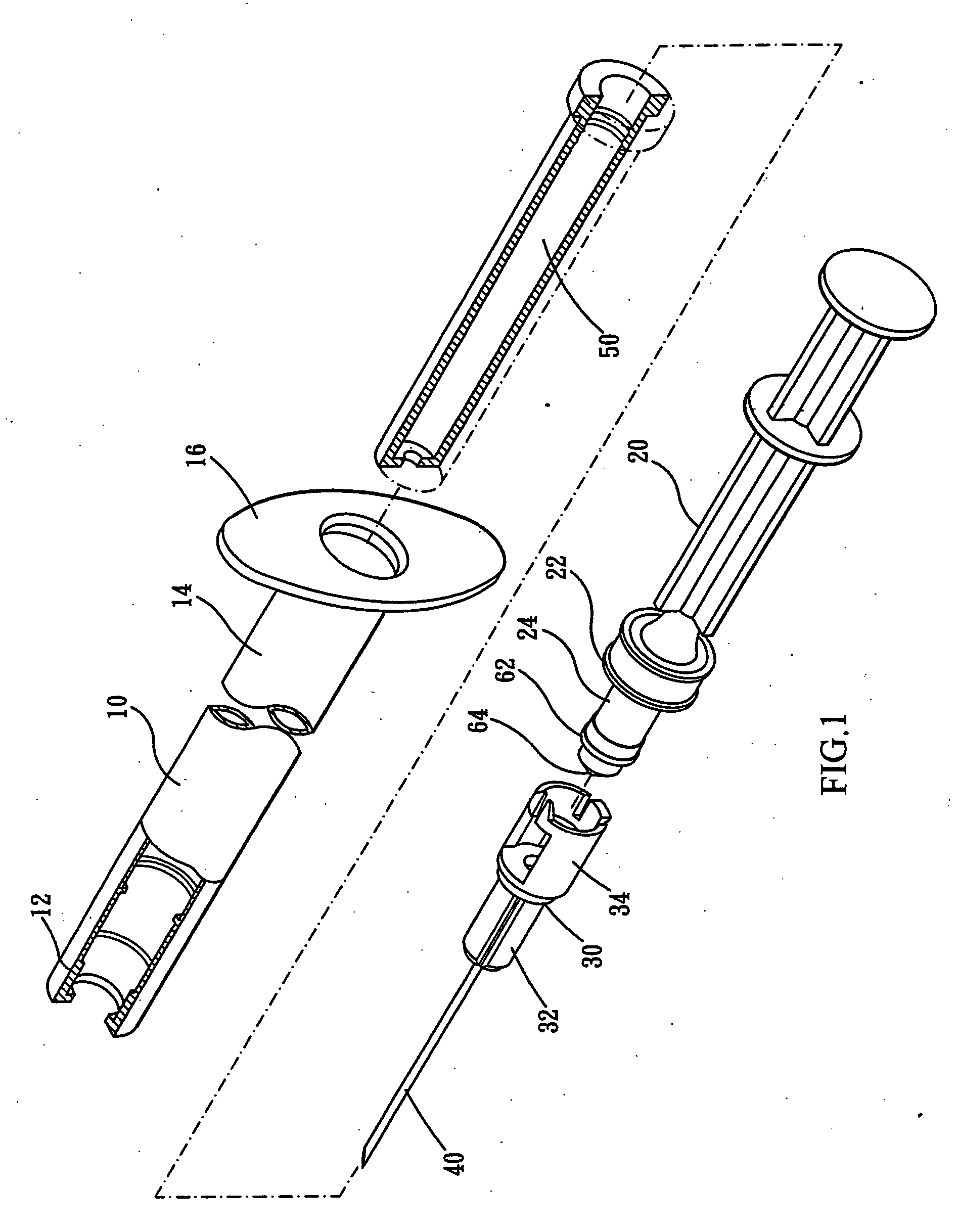
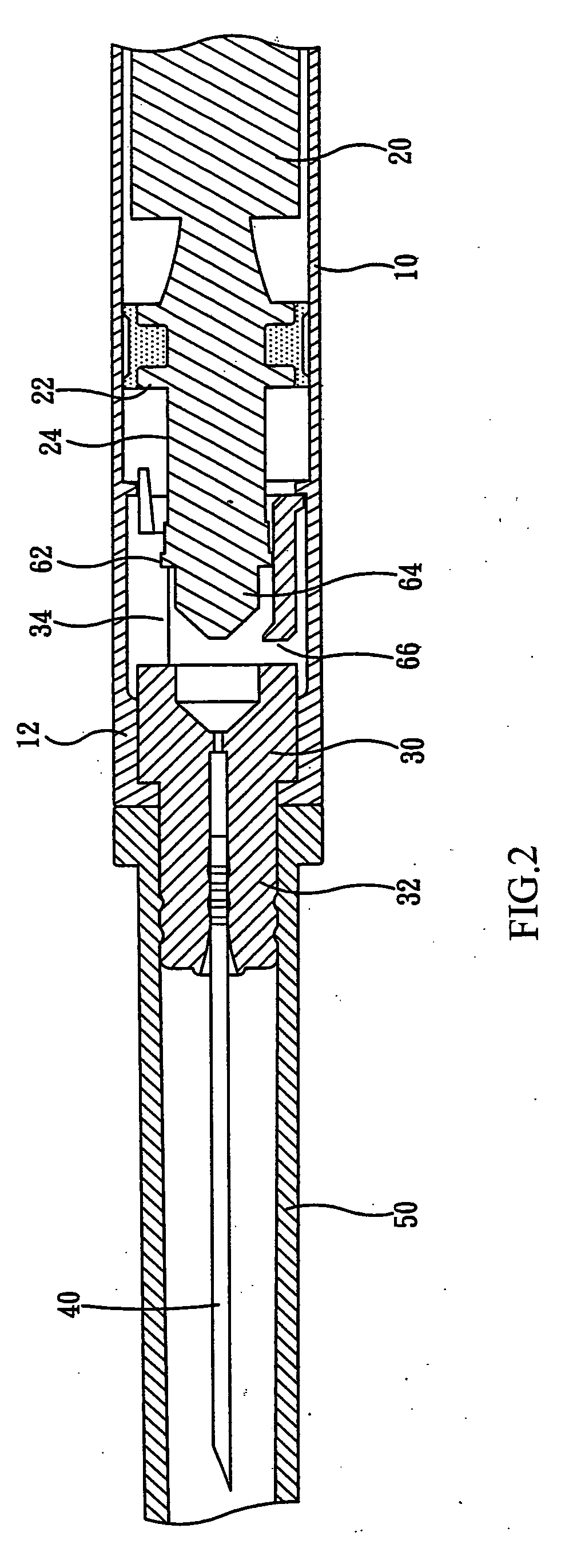
[0023]FIGS. 1 and 2 are respectively explosive and combinative views of the first embodiment in accordance with the present invention. A syringe comprises a barrel 10, a plunger 20, a needle adapter 30, a needle 40 disposed at one end of the needle adapter 30, and a sheath 50 used to cover the needle 40.

[0024] The barrel 10 is a hollow tube having a stepped cross section at its front lumen 12 and an outer extension 16 at its rear lumen 14.

[0025] The needle-adapter 30 is arranged in the front lumen 12 of the barrel 10 and stopped by the stepped inner wall. One end of the plunger 20 comprises an exterior ring 22 connected with a piston and inserted in the barrel 10. By pushing the plunger 20, the exterior ring 22 will move toward the needle-adapter 30.

[0026] The exterior ring 22 of the plunger 20 further comprises a shaft 24 at its front end. The fore part of the shaft 24 is surrounded with an extruding ring 62 and a protrusion 64 is formed at the front end thereof.

[0027] The needl...

third embodiment

[0033]FIG. 10 shows the needle-adapter of the third embodiment, which is similar to that shown in FIG. 9. Difference between them is that two cantilever 170 with tongues 180 at respective free end thereof are disposed in one end of the rectangle hole 140.

second embodiment

[0034]FIGS. 11 and 12 are cross sections of the syringe of the second embodiment in use. During injection, the plunger 20 is pushed into the connecting tube 94 of the needle-adapter 90. The protrusion 110 is then fitted into the aperture 120, and the extruding ring 100 is engaged into the receiving groove 130. Meanwhile, the tongue 160 is forced by the ring 82, so that the cantilever 150 can bend toward the center of the rectangle hole 140.

[0035]FIG. 13 shows the needle and needle adapter retracted into the barrel according to the second embodiment. When the plunger 80 is pulled rearward, the needle-adapter 90 is retracted back into the barrel 70 with the plunger 80 because of engagement between the extruding ring 82 and the receiving groove 130. Particularly, the barrel 70 with a larger inner diameter has enough space for the needle-adapter 90 to tilt therein. The cantilever 150 tilts as the tongue 160 of the needle-adapter 90 is forced by the exterior ring 82 of the plunger 80. Th...


PUM


Abstract

The present invention discloses a mechanism for tilting a retractable needle, in which a needle adapter housed within a barrel comprises a connecting tube with a receiving groove on inner wall. The connecting tube forms a rectangle hole on the wall, and a cantilever with at least one tongue is formed between the rectangle hole and the rear portion of the connecting tube. The plunger fitted in the barrel comprises an extruding ring at a front end thereof. When the plunger is pushed forwardly into the connecting tube of the needle-adapter, an exterior ring of the plunger connected to with a piston will force the tongue to bend the cantilever toward the center of the open area, and engage the extruding ring into the receiving groove. When the plunger is pulled backward, the needle-adapter and the needle will be retracted into the barrel. Meanwhile, the needle will tilt as the tongue is forced against exterior ring by the cantilever, and the needle point is therefore close to the inner wall of the barrel. Accordingly, exposure of the needle point due to carelessly pushing the plunger can be prevented.

Description

BACKGROUND OF THE INVENTION [0001] 1. Field of the Invention [0002] The present invention relates to a retractable mechanism and particularly, to a mechanism applied to a retractable safety syringe and capable of tilting the needle during retracting, so that injury by the needle point can be avoided. [0003] 2. Description of Related Prior Arts [0004] In general, a syringe is composed of a hollow barrel a plunger. The barrel is associated with a needle and contains liquid. One end of the plunger is disposed with a piston for fitting in the barrel, and the other end is exposed from the barrel. By pushing the plunger, the liquid contained in the barrel will be injected from the needle point. [0005] For the conventional syringe, the needle is necessary to be covered by a sheath before separated from the barrel. However, such behavior has a lot of risk of stabbing for the operator. [0006] Taiwan Patent No. 394027 therefore provides a safety syringe, in which a needle with a support is ho...

Claims


Application Information

Patent Timeline
Patent Type & Authority Applications(United States)
IPC IPC(8): A61M5/00A61M5/32
CPCA61M2005/3224A61M5/322
Inventor LOU, JIN-RONG
Owner INTAI TECH CORP
Learn More