Massage device

a technology of massaging device and hammer, which is applied in the field of hammersaws, can solve the problems of unreliable use, increased manufacturing cost, and several prior art problems, and achieve the effect of improving the reliability of us

Inactive Publication Date: 2006-09-28
CHEN KO PO
View PDF0 Cites 4 Cited by
  • Summary
  • Abstract
  • Description
  • Claims
  • Application Information

AI Technical Summary

Benefits of technology

[0010] In another aspect of the present invention, the urging member is a member having a substantially rounded periphery in more that half of its surface.

Problems solved by technology

However, the prior art suffered from several disadvantages.
For example, the locking mechanism is typically relatively complex in components resulting in an increase in the manufacturing cost, unreliable in use, and troublesome to manipulate or operate.

Method used


Image

  • Massage device
  • Massage device
  • Massage device

Examples


Embodiment Construction

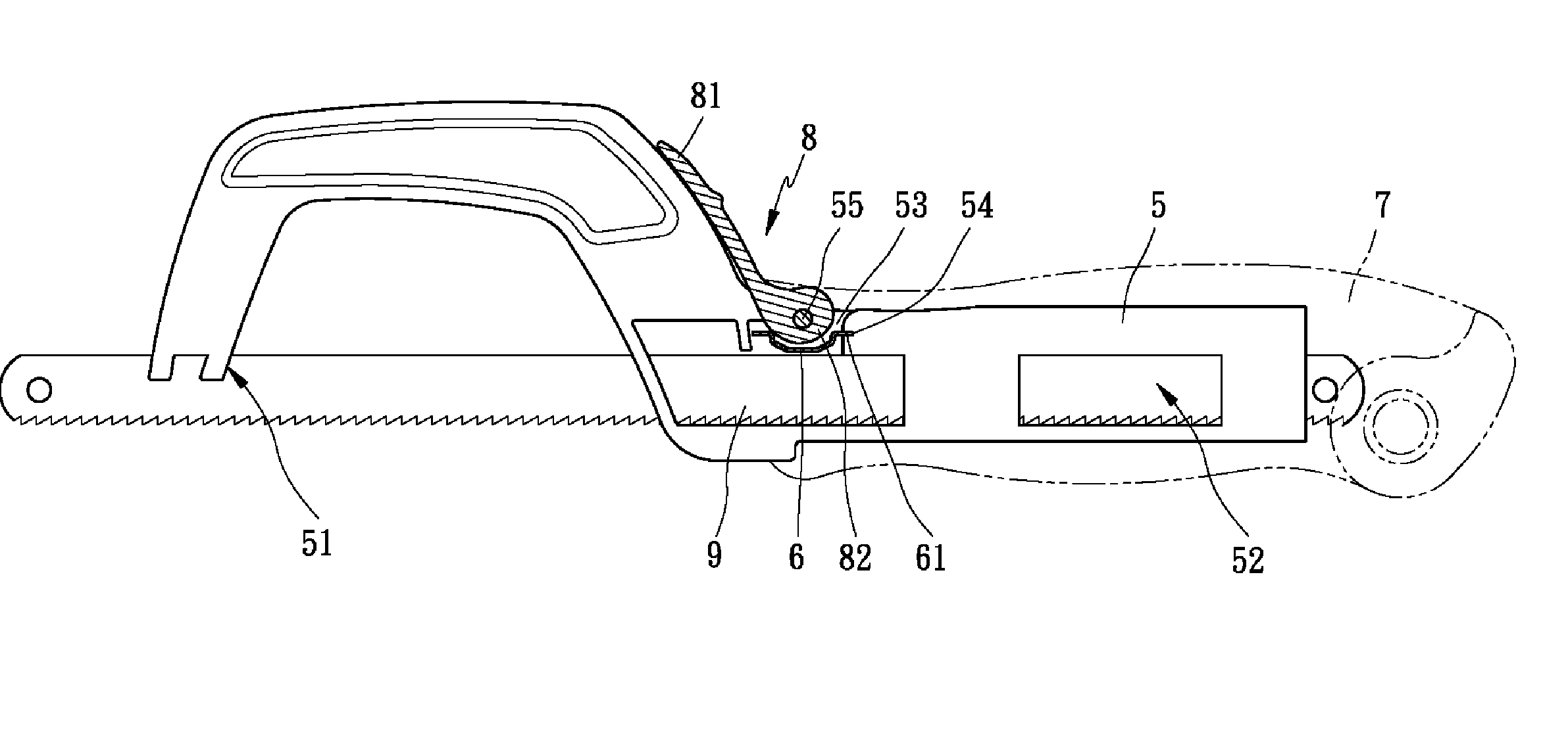
[0023] Referring to FIGS. 3, 4, and 5, there is shown a hacksaw having a mechanism for locking an adjustable blade thereof in accordance with the invention. A guide groove 51 is provided in a toe of the frame 5 with a forward portion of the blade 9 passed through and fastened therein. A front first cavity 53 is provided in a heel of the frame 5 and a rear second cavity 52 is provided in a tang portion thereof in which both the cavities 52 and 53 are in communication, a front end of the first cavity 53 is in communication with the external, and a rear end of the second cavity 52 is also open. A slit 54 is provided in one side of a narrow upper opening of the first cavity 53. A curved resilient member 6 has two flat ends 61 in which one end 61 is snugly inserted into the slit 54 for fastening and the remaining portion is provided in the first cavity 53. The tang portion of the frame 5 is provided in a handle 7. The handle 7 comprises a rectangular opening 71 on its top surface. The op...


PUM

PropertyMeasurementUnit
thickaaaaaaaaaa
resilientaaaaaaaaaa
lengthaaaaaaaaaa

Abstract

Provided is a hacksaw comprising a front cavity in a tang of the frame, a resilient member having one end fastened in one side of the cavity, a handle for receiving the tang and a top opening aligned with the cavity, a pivotal lock lever disposed in the opening and comprising an arm and an end urging member (e.g., cam), a blade inserted through the cavity and the tang into the handle. A thin portion of the urging member is disposed proximate the resilient member and the resilient member is disengaged from the blade when the arm is disposed in a forward position. To the contrary, a thick portion of the urging member is pressed down on the resilient member for fastening a back of the blade when the arm is disposed in a rearward position.

Description

BACKGROUND OF THE INVENTION [0001] 1. Field of Invention [0002] The present invention relates to hacksaws and more particularly to an improved mechanism for locking an adjustable blade of hacksaw. [0003] 2. Related Art [0004] Hacksaws with adjustable blade are well known. For example, Taiwanese Patent No. 91,204,426 discloses a mechanism for locking an adjustable blade 4 of hacksaw as shown in FIGS. 1 and 2. A guide groove 11 is provided in a toe of the frame with a forward portion of the blade 4 passed through (see FIG. 2). A cavity 13 is provided in the front portion of a handle 1. An upward directed channel 14 is provided for communicating a top of the cavity 13 with the external. A curved recess 15 is formed on a top surface of the handle 1 with an opening of the channel 14 disposed on its bottom. A sliding member 2 is disposed in the cavity 13. The sliding member 2 comprises a transverse hollow portion 21 as a part of a tunnel 12 in the handle 1 with a portion of the blade 4 pa...

Claims


Application Information

Patent Timeline
Patent Type & Authority Applications(United States)
IPC IPC(8): B27B21/06
CPCB23D51/10B27B21/02
Inventor CHEN, KO-PO
Owner CHEN KO PO
Why Eureka
Try Eureka