
Power converter employing integrated magnetics with a current multiplier rectifier and method of operating the same

a power converter and current multiplier technology, applied in the field of power electronics, can solve the problems of increasing the volume and weight of the power, sluggish transient response to dynamic load conditions, and insufficient two-phase interleaved current multiplier power converters to meet the switching ripple specifications of inductance,

Active Publication Date: 2006-08-24
MYPAQ HLDG LTD
View PDF99 Cites 117 Cited by
  • Summary
  • Abstract
  • Description
  • Claims
  • Application Information

AI Technical Summary

Benefits of technology

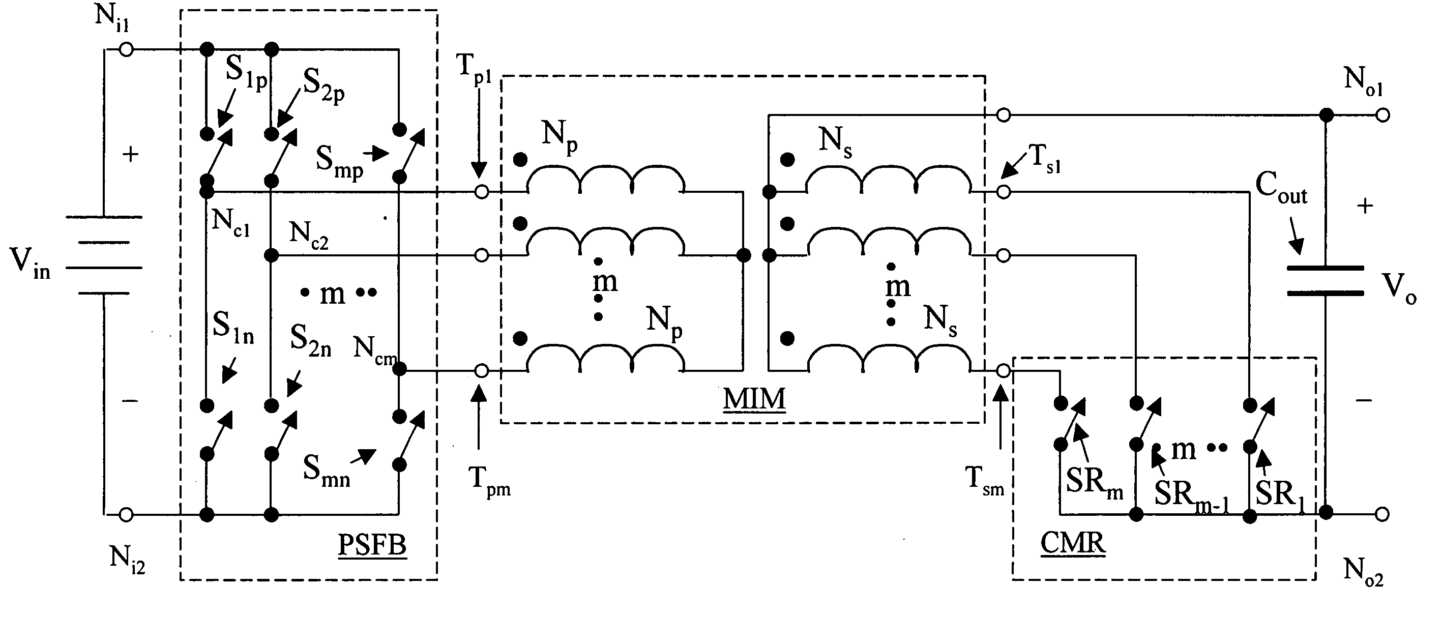
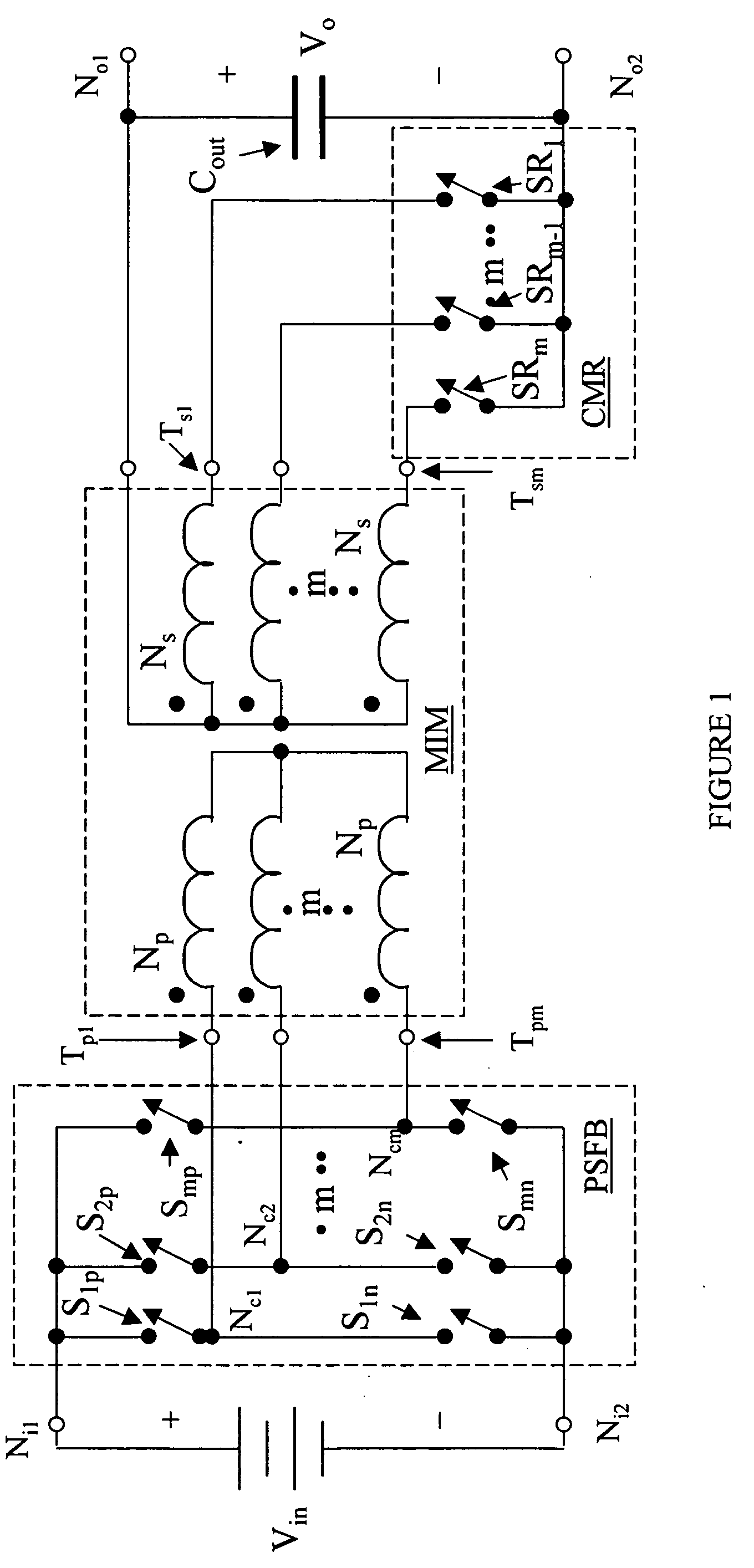
[0012] These and other problems are generally solved or circumvented, and technical advantages are generally achieved, by advantageous embodiments of the present invention that include a power converter having input and output nodes and a method of operating the same. In one embodiment, the power converter includes a switching circuit including first, second and third active phase legs. Each of the first, second and third active legs includes a first switch coupled to one of the input nodes and a second switch coupled to another of the input nodes and has a common switching node therebetween. The power converter further includes a magnetic device including first, second and third primary windings, and first, second and third secondary windings. The first, second and third primary windings are coupled to the common switching node of the first, second and third active phase legs, respectively. The power converter still further includes a rectifier including first, second and third rectifier elements interposed between the first, second and third secondary windings, respectively, and one of the output nodes.

Problems solved by technology

For applications where higher currents (typically greater than 50 amps (“A”)) are required at low (typically less than 3.3 volts (“V”)) to moderate (typically about 12 V) voltages at high efficiency and power density, a two-phase interleaved current multiplier power converter might be inadequate to meet switching ripple specifications on inductor currents and output voltage.
A larger output capacitor can reduce the output ripple voltage, but will increase the volume and weight of the power converter and result in sluggish transient response to dynamic load conditions.
Utilizing multiple discrete E-cores to implement multiphase interleaved current multiplier power converters and simply paralleling multiple power converters, however, increases component count and interconnect losses, resulting in poor power density and efficiency.
An additional limitation to using E-cores for high current applications is the detrimental effects of fringing flux due to the limited cross-sectional area of a gapped center leg.
This results in increased losses (e.g., denoted by I2R, wherein “I” represents the current and “R” represents the resistance) in the windings and reduced efficiency.
To reduce the induction of eddy currents due to fringing flux, windings are placed a safe distance from the air gap, resulting in poor utilization of the core window area.
In addition, fringing flux represents a loss of inductance, which results in increased switching ripple in the winding currents, leading to higher losses and poorer efficiencies.
A power converter that combines the advantages of an interleaving, multiphase power converter topology with integrated magnetics and a current multiplying rectifier is not presently available for the more severe applications that lie ahead.

Method used


Image

  • Power converter employing integrated magnetics with a current multiplier rectifier and method of operating the same
  • Power converter employing integrated magnetics with a current multiplier rectifier and method of operating the same
  • Power converter employing integrated magnetics with a current multiplier rectifier and method of operating the same

Examples


Embodiment Construction

[0031] The making and using of the presently preferred embodiments are discussed in detail below. It should be appreciated, however, that the present invention provides many applicable inventive concepts that can be embodied in a wide variety of specific contexts. The specific embodiments discussed are merely illustrative of specific ways to make and use the invention, and do not limit the scope of the invention. Unless otherwise provided, like designators for devices employed in different embodiments illustrated and described herein do not necessarily mean that the similarly designated devices are constructed in the same manner or operate in the same way. It should also be understood that the use of the terms such as “first” and “second” are employed for purposes of explanation and clarity, and reversing such designations when referring to device(s) is well within the broad scope of the present invention.

[0032] The present invention will be described with respect to an exemplary e...


PUM


Abstract

A power converter having input and output nodes and a method of operating the same. In one embodiment, the power converter includes a switching circuit including first, second and third active phase legs. Each of the first, second and third active legs includes a first switch coupled to one of the input nodes and a second switch coupled to another of the input nodes and has a common switching node therebetween. The power converter further includes a magnetic device including first, second and third primary windings, and first, second and third secondary windings. The first, second and third primary windings are coupled to the common switching node of the first, second and third active phase legs, respectively. The power converter still further includes a rectifier including first, second and third rectifier elements interposed between the first, second and third secondary windings, respectively, and one of the output nodes.

Description

[0001] This application claims the benefit of U.S. Provisional Application No. 60 / 651,059, entitled “Isolated Current Multiplier Rectifier,” filed on Feb. 8, 2005, which is incorporated herein by reference.TECHNICAL FIELD [0002] The present invention is directed, in general, to power electronics and, in particular, to power converters using a switching circuit, integrated magnetics and a current multiplier rectifier. BACKGROUND [0003] A switched-mode power converter (also referred to as a “power converter”) is an electronic power processing circuit that converts an input voltage waveform into an output voltage waveform. The waveforms are typically, but not necessarily, dc waveforms, generated by periodically switching power switches or switches coupled to an inductive circuit element. The switches are generally controlled with a conduction period “D” referred to as a “duty cycle.” The duty cycle is a ratio represented by the conduction period of a switch to a switching period thereo...

Claims


Application Information

Patent Timeline
Patent Type & Authority Applications(United States)
IPC IPC(8): H02M3/335
CPCH02M3/33592H02M3/337H02M3/3376Y02B70/1475Y02B70/10H02M3/33573
Inventor CHANDRASEKARAN, SRIRAMMEHROTRA, VIVEK
Owner MYPAQ HLDG LTD
Learn More