
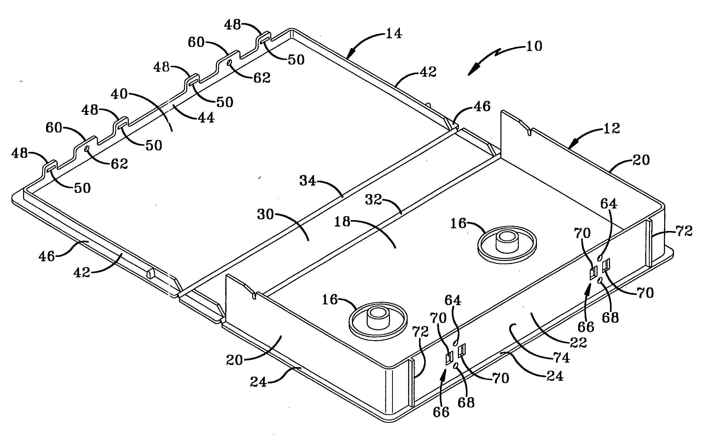
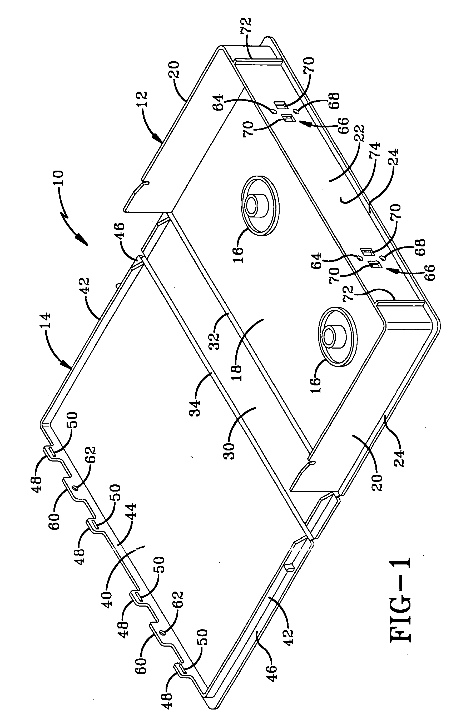
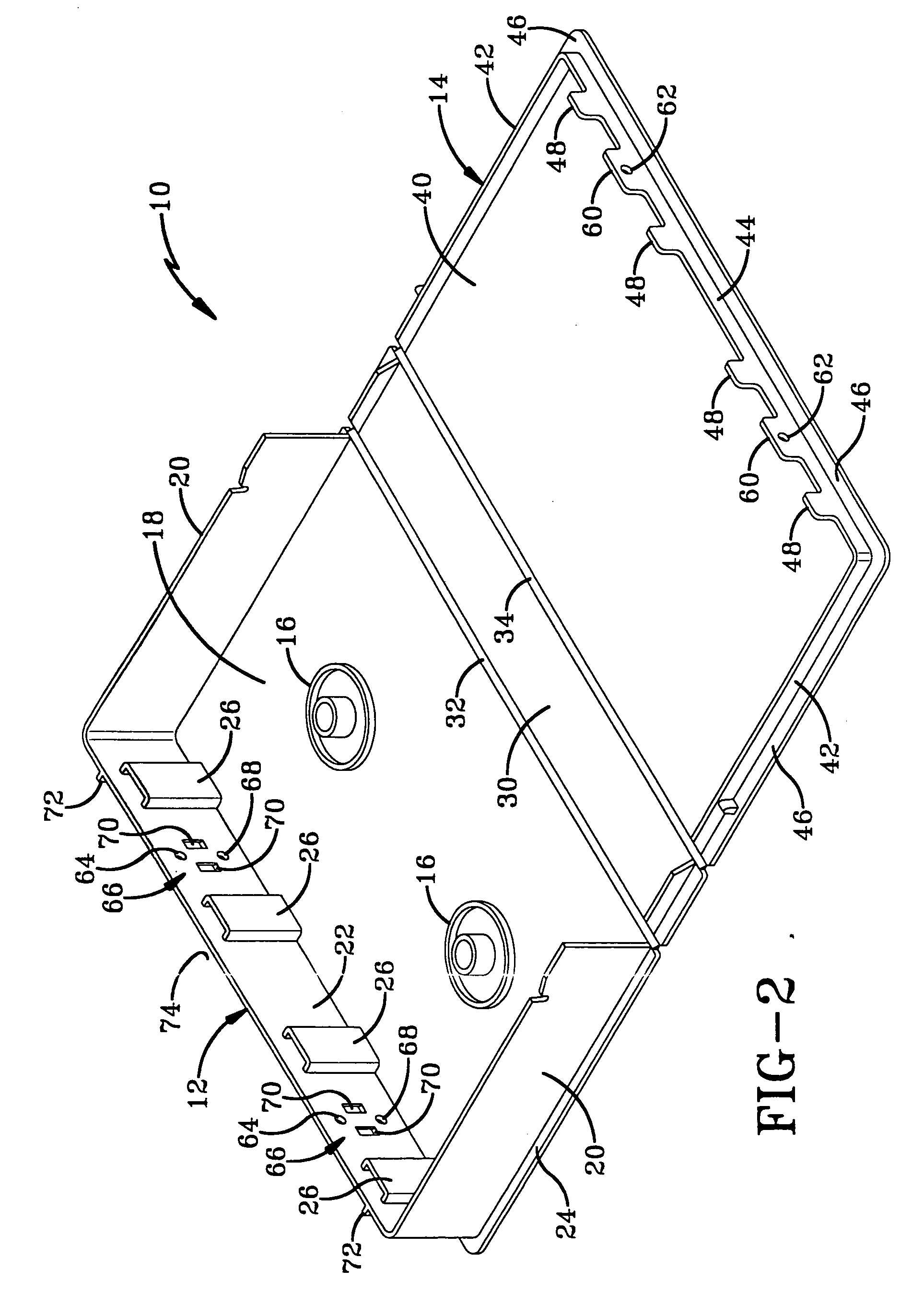
Lockable media storage box with lock and key

a technology of lock and key and storage box, which is applied in the field of media storage boxes, can solve the problems of difficult positioning of the eas tag in such a position, and the cost of manufacturing the lock and storage box must not be prohibitiv

Inactive Publication Date: 2006-08-24
AUTRONIC PLASTICS
View PDF6 Cites 4 Cited by
  • Summary
  • Abstract
  • Description
  • Claims
  • Application Information

AI Technical Summary

Benefits of technology

The present invention is a lockable media storage box with a base and lid that can be locked closed using a locking member. The lid and base have matching locking holes that align when the lid is closed. The lock member is slidably carried on one of the lids or base and can be removably mounted to the storage container. The invention also provides magnetically actuated and mechanically actuated locks. The technical effect of this invention is to provide a secure and easy-to-use way to lock a media storage box.

Problems solved by technology

Placement of the EAS tag in such a position is, however, difficult because a storage container provides few, if any, areas where the EAS tag may be hidden.
Although the storage box and lock must be relatively strong, the cost of manufacturing the lock and storage box must not be prohibitive.

Method used


Image

  • Lockable media storage box with lock and key
  • Lockable media storage box with lock and key
  • Lockable media storage box with lock and key

Examples


first embodiment

[0128] a lock for either box 10 or 80 is depicted in FIGS. 3 through 5 and is indicated generally by the numeral 110. Lock 110 generally includes a body 112, at least one locking pin 114, and at least one locking finger 116. In general, at least one locking pin 114 prevents box 10 or 80 from being opened when lock 110 lockably engages box 10 or 80. Locking fingers 116 provide the locked connection between lock 110 and box 10 or 80. Body 112 also defines a storage cavity 118. An EAS tag 120 may be disposed fully within cavity 118 such that no portion of EAS tag 120 protrudes beyond the boundaries of body 112 as may be seen in FIG. 4. Body 112 also defines a key hole 130 that is disposed in body 112 to align with each locking finger 116.

[0129] In addition to locking pins 114 and locking fingers 116, lock 110 also includes a cantilevered arm 132 having an anchored end 134 and a free end 136 disposed adjacent one of locking fingers 116. Cantilevered arms 132 provide visual deterrents to...

second embodiment

[0138] a lock for either box 10 or 80 is depicted in FIGS. 17 through 19 and is indicated generally at 210. Lock 210 generally includes a body 212, at least one locking pin 214, and at least one locking finger 216. In general, at least one locking pin 214 prevents box 10 or 80 from being opened when lock 210 lockingly engages box 10 or 80. Locking fingers 216 provide the locked connection between lock 210 and box 10 or 80. Body 212 also defines a storage cavity 218. An EAS tag 220 may be disposed fully within cavity 218 such that no portion of EAS tag 220 protrudes beyond the boundaries of body 212 as is seen in FIGS. 19 and 22. Body 212 also defines a pair of key slots 230 that are disposed on either end of lock 210. Each locking pin 214 is preferably fabricated from a metal that is anchored in body 212 of lock 210. Metal is preferred because it may not easily be sheared but other suitable plastics may be used in place of metal locking pins 214 without departing from the scope of t...


PUM

PropertyMeasurementUnit
areaaaaaaaaaaa
strengthaaaaaaaaaa
perimeteraaaaaaaaaa

Abstract

A lockable media storage box and lock and key combination includes a box having a base and a lid hingedly connected to the base and movable between opened and closed positions. A locking mechanism is movable between locked and unlocked positions to lock and unlock the container. The lock includes lock pins that slide through aligned lock holes in the base and the lid.

Description

CROSS-REFERENCE TO RELATED APPLICATIONS [0001] This application is a continuation of U.S. Pat. No. 6,966,438 which is a continuation application of U.S. Pat. No. 6,598,742 which is a continuation-in-part application of U.S. Pat. No. 6,601,701, which is a continuation-in-part application of U.S. Pat. No. 6,135,280, which is a continuation of U.S. Pat. No. 5,944,185. The disclosures of U.S. Pat. No. 6,966,438 are incorporated herein by reference.BACKGROUND OF THE INVENTION [0002] 1. Technical Field [0003] The present invention is generally related to media storage boxes and, more particularly, to a lockable media storage box. [0004] 2. Background Information [0005] Renting items of recorded media such as video cassettes and video games has become immensely popular in recent times given the ever increasing number of items available for home viewing and use as well as the decrease in price of the machines that play the media. Typical rental stores display the items available for rental ...

Claims


Application Information

Patent Timeline
Patent Type & Authority Applications(United States)
IPC IPC(8): A45C13/10E05B17/00E05B47/00E05B73/00G11B23/023G11B33/04
CPCE05B17/0062E05B73/0023E05B73/0058G11B23/0233G11B33/0427Y10T70/5004Y10T70/5544Y10T70/5031
Inventor BELDEN, DENNIS D. JR.BURDETT, RONALD K.JAEB, MICHAEL S.MARSILIO, RONALD M.SEDON, NICHOLAS M.BYRNE, JAMES M.
Owner AUTRONIC PLASTICS
Learn More