Internal structure stabilization system for spanning three or more structures

a stabilization system and structure technology, applied in the field of bone stabilization systems, can solve the problems of reducing disc height, dehydration or herniation, reducing disc height, and loosing height of intervertebral discs

Inactive Publication Date: 2006-08-03
THEKEN SURGICAL LLC
View PDF99 Cites 361 Cited by
  • Summary
  • Abstract
  • Description
  • Claims
  • Application Information

AI Technical Summary

Benefits of technology

[0011] The present invention also describes an instrument for positioning a bone anchor in space between a first and second bone anchor assemblies. The instrument includes a mechanism for defining an arc corresponding to the predefined arc of the connector being used. The mechanism for defining an arc is connected to first and second ends which can be removably connected to the first and second bone anchors, and includes a length defining mechanism which allows the spacing between the first and second ends to be matched to the spacing between the first and second bone anchors. A member is movably connected to the arc defining mechanism, which can removably hold an extension used in placing the third bone anchor in the correct position in space.

Problems solved by technology

Over time, or because of accidents, the intervertebral discs loose height, become cracked, dehydrated, or herniated.
The result is that the disc height is reduced leading to compression of the nerve bundles, causing pain and in some cases damage to the nerves.
One problem occurs in systems designed to span three or more vertebrae.
It is currently difficult to properly position a rod between two anchors in adjacent vertebrae.
This problem is magnified greatly when a rod is fitted across three or more adjacent vertebrae.
Problems occur in maintaining each of the anchors in proper alignment to receive the rod and are compounded by imparting a curve in the rod to account for the natural curvature of the spine, in properly positioning the anchors to accept a pre-curved rod.

Method used


Image

  • Internal structure stabilization system for spanning three or more structures
  • Internal structure stabilization system for spanning three or more structures
  • Internal structure stabilization system for spanning three or more structures

Examples


Embodiment Construction

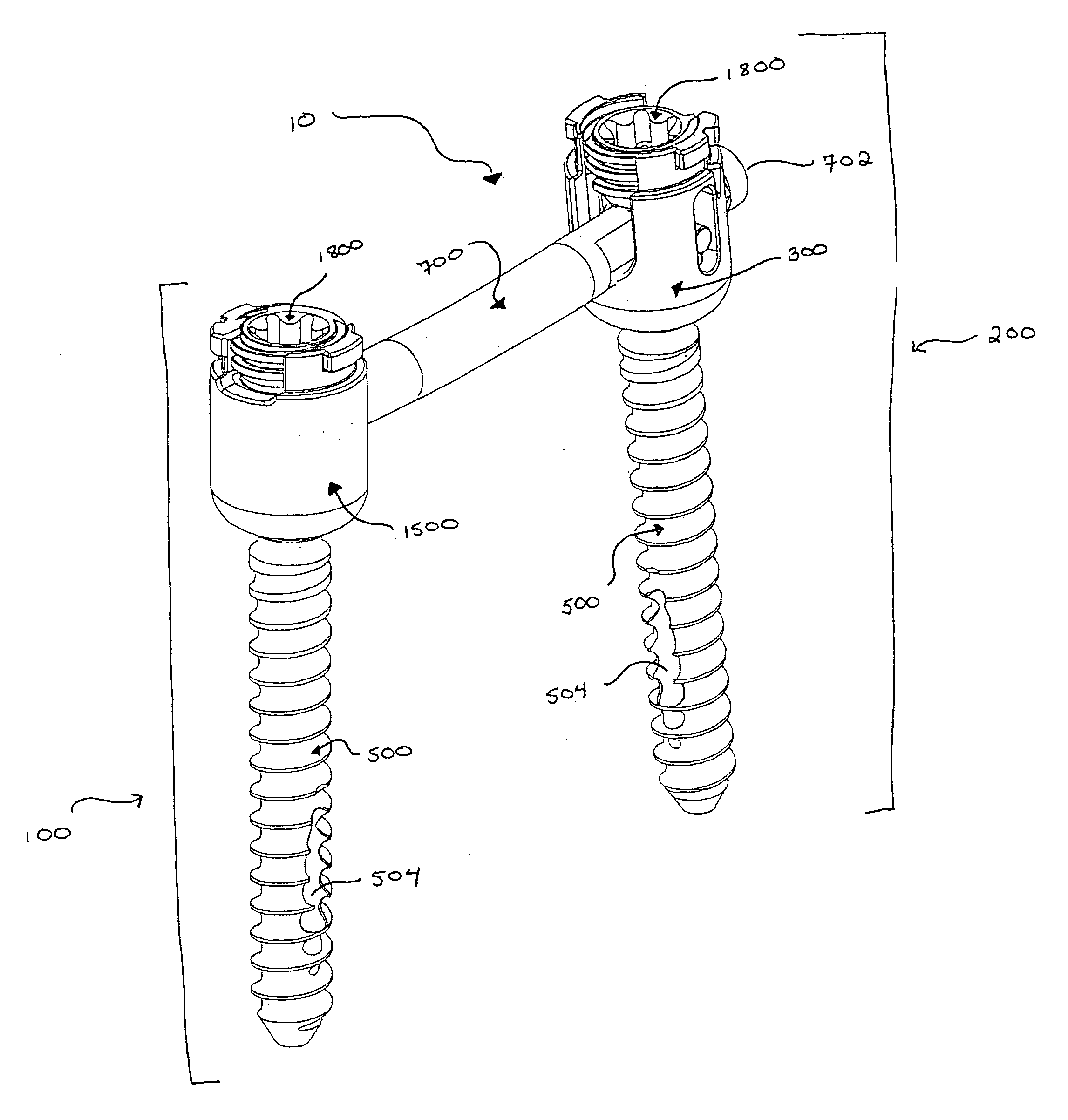
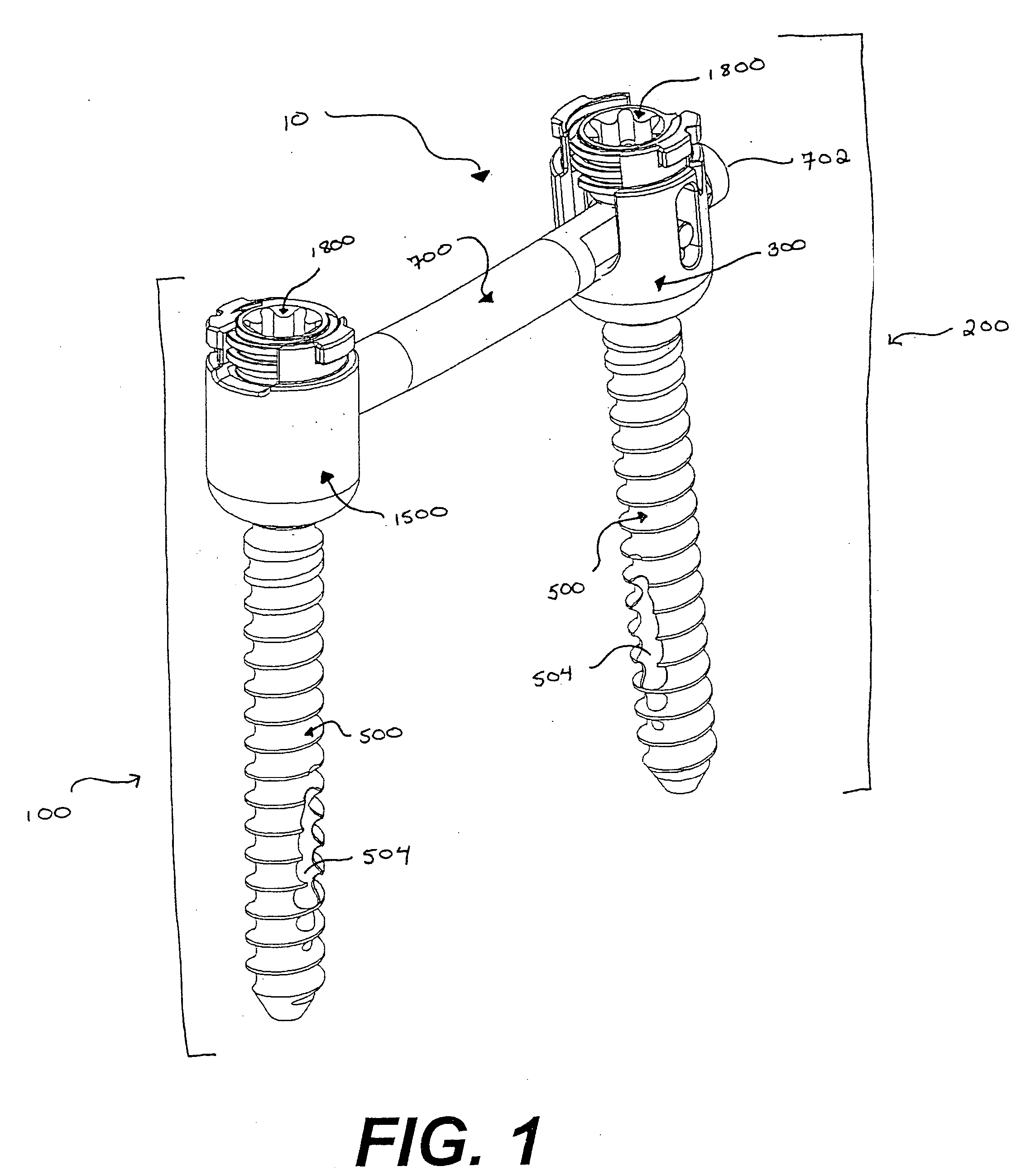
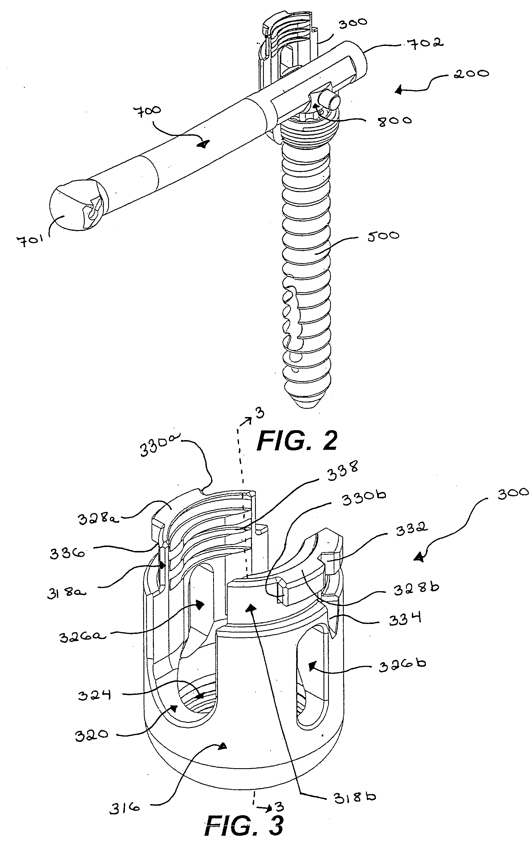
[0095] To better understand the devices, assemblies, tools, and methods described below, and understanding of the procedure through which the back stabilization of the present invention is placed into the vertebrae of a patient is required. Reference is made to the figure numbers where specific embodiments of the devices, assemblies, tools and methods are described in greater detail to aid in the understanding of those particular items.

[0096] An operation to insert a pedicle screw assembly into a patient's back to immobilize certain vertebrae in order to allow bone grafts to ultimately fuse those vertebrae begins with the surgeon inserting a standard bone biopsy needle into the pedicle of a first vertebra and using the bone biopsy needle to place a guide wire where the first pedicle screw should be inserted. Using the guide wire, progressively larger tissue expanders are inserted into the patient to expand, or dilate, the incision to the size necessary to accommodate the instrument...


PUM


Abstract

A method and system are described for immobilizing three or more vertebrae. The system includes a first bone anchor assembly, a second bone anchor assembly including a connector having a predefined arc, and at least a third bone anchor assembly. The first and second bone anchor assembly are inserted into the pedicles of vertebrae spanning at least a third vertebra. The third bone anchor assembly is positioned into the third vertebra between the first and second bone anchor assemblies using an arc defining instrument which is used to locate the proper position for the third bone anchor assembly based on the predefined arc of the connector. Once the third bone anchor assembly is in place the connector is rotated into position and captured by the first and third bone anchor assemblies.

Description

TECHNICAL FIELD [0001] This invention relates to bone stabilization systems, and more particularly to systems and methods for immobilizing bony structures such as vertebrae, and even more particularly a device designed to span three or more bony structures. BACKGROUND OF THE INVENTION [0002] The human spine provides a vast array of functions, many of which are mechanical in nature. The spine is constructed to allow nerves from the brain to pass to various portions of the middle and lower body. These nerves, typically called the spinal cord, are located in a region within the spine called the spinal canal. Various nerve bundles emerge from the spine at different locations along the lateral length of the spine. In a healthy spine, these nerves are protected from damage and / or undue pressure thereon by the structure of the spine itself. [0003] The spine has a complex curvature made up of a plurality (24 in all) of individual vertebrae separated by intervertebral discs. These discs hold...

Claims


Application Information

Patent Timeline
Patent Type & Authority Applications(United States)
IPC IPC(8): A61F2/30A61B17/70A61B17/88
CPCA61B5/103Y10T74/22A61B5/4504A61B17/1604A61B17/1655A61B17/1757A61B17/320016A61B17/3417A61B17/3421A61B17/3468A61B17/7002A61B17/7005A61B17/701A61B17/7011A61B17/7032A61B17/7037A61B17/7038A61B17/704A61B17/7082A61B17/7085A61B17/7091A61B2017/320044A61B2019/461A61B2019/467A61B5/6878A61B5/6882A61B5/107A61B2090/067A61B2090/061
Inventor SPITLER, JAMESCOLLERAN, DENNIS
Owner THEKEN SURGICAL LLC
Why Eureka
Try Eureka