
Universal safety cap

Inactive Publication Date: 2006-08-03
MAZZ ENTERPRISES
View PDF23 Cites 57 Cited by
  • Summary
  • Abstract
  • Description
  • Claims
  • Application Information

AI Technical Summary

Benefits of technology

[0022] The present invention covers three different embodiments of a universal safety cap. In the first embodiment, the safety cap comprises a plurality of rigid plates, a foam insert, and an outer covering. The rigid plates are embedded within the foam insert, and the outer covering is preferably comprised of fabric. The foam insert and the rigid plates each comprise(s) a plurality of preferable but optional

Problems solved by technology

Despite the relative perceived safety of baseball as opposed to some other sports, there have been a number of injuries and even deaths caused by a baseball hitting a player's head at a high speed and / or at an area of the head (such as the temple) that can cause serious injury.

Method used


Image

  • Universal safety cap
  • Universal safety cap
  • Universal safety cap

Examples


first embodiment

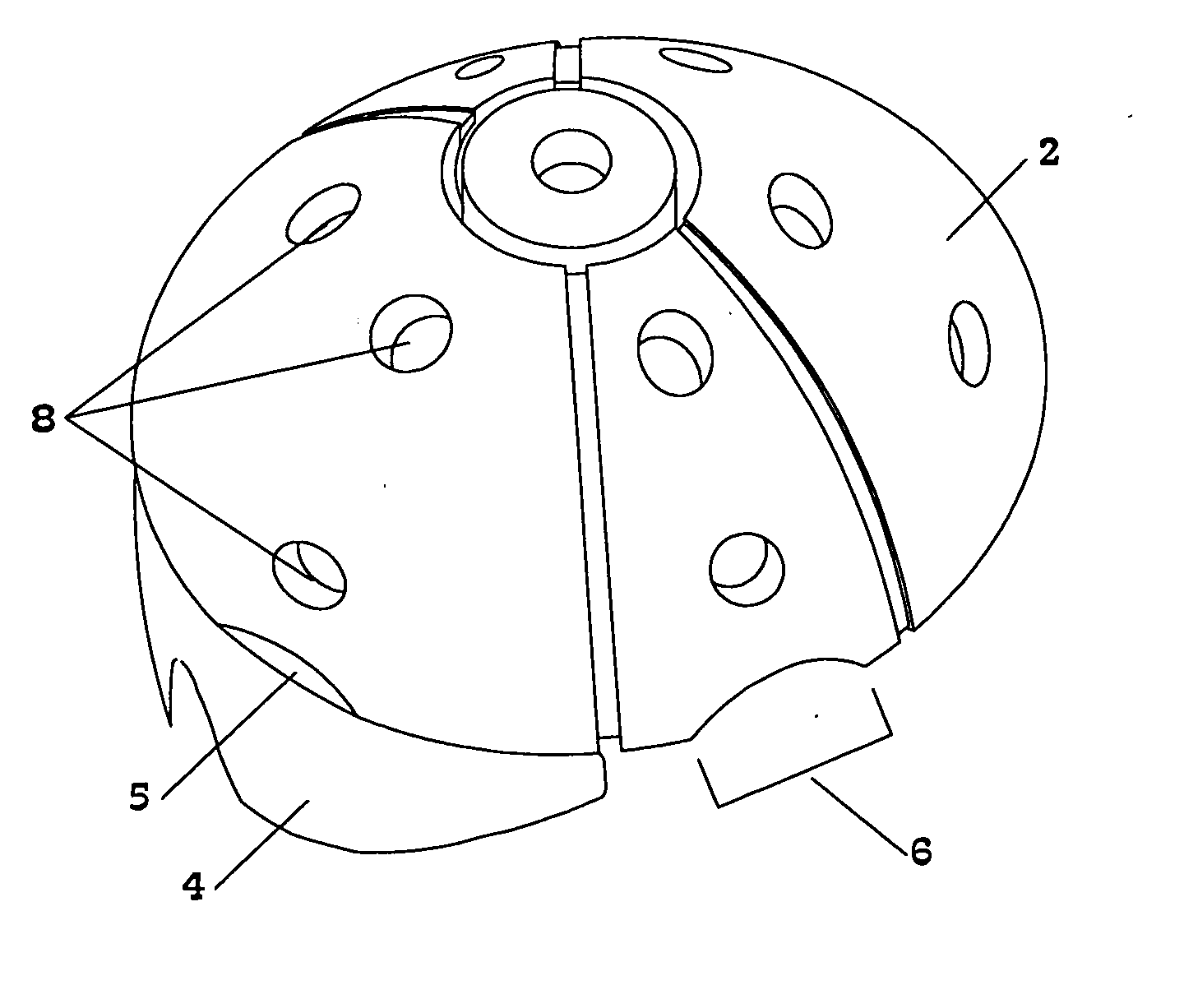
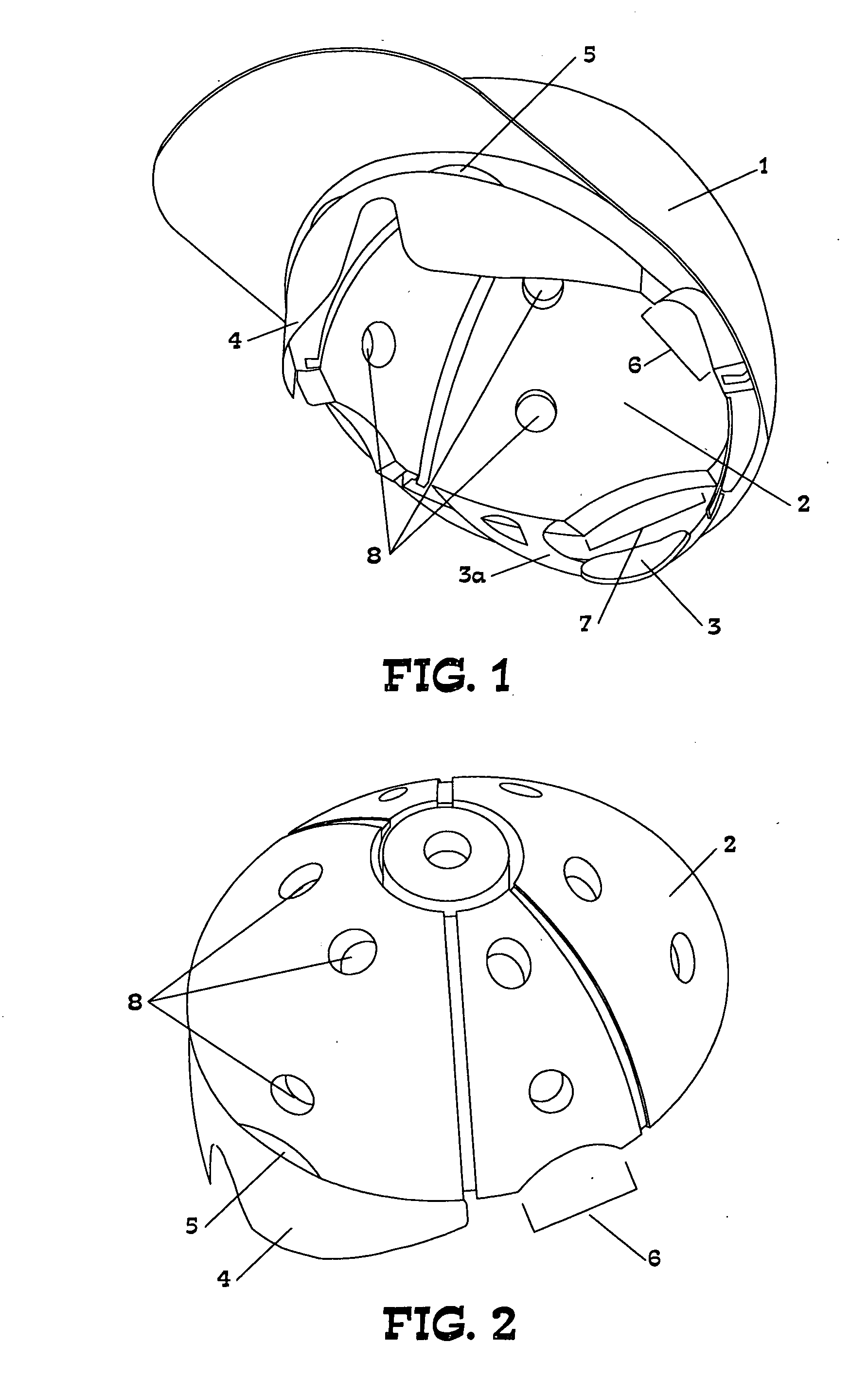
[0060]FIG. 2 is a perspective view of the present invention without the outer covering 1. This figure shows more clearly the optional ventilation holes 8 in the foam insert 2. It also shows the eye protector 4, one of the eye cutouts 5, and one of the ear cutouts 6. The particular configuration of the ventilation holes 8 shown in this figure is for illustrative purposes only; the present invention is not limited to any particular shape, number or configuration of ventilation holes 8.

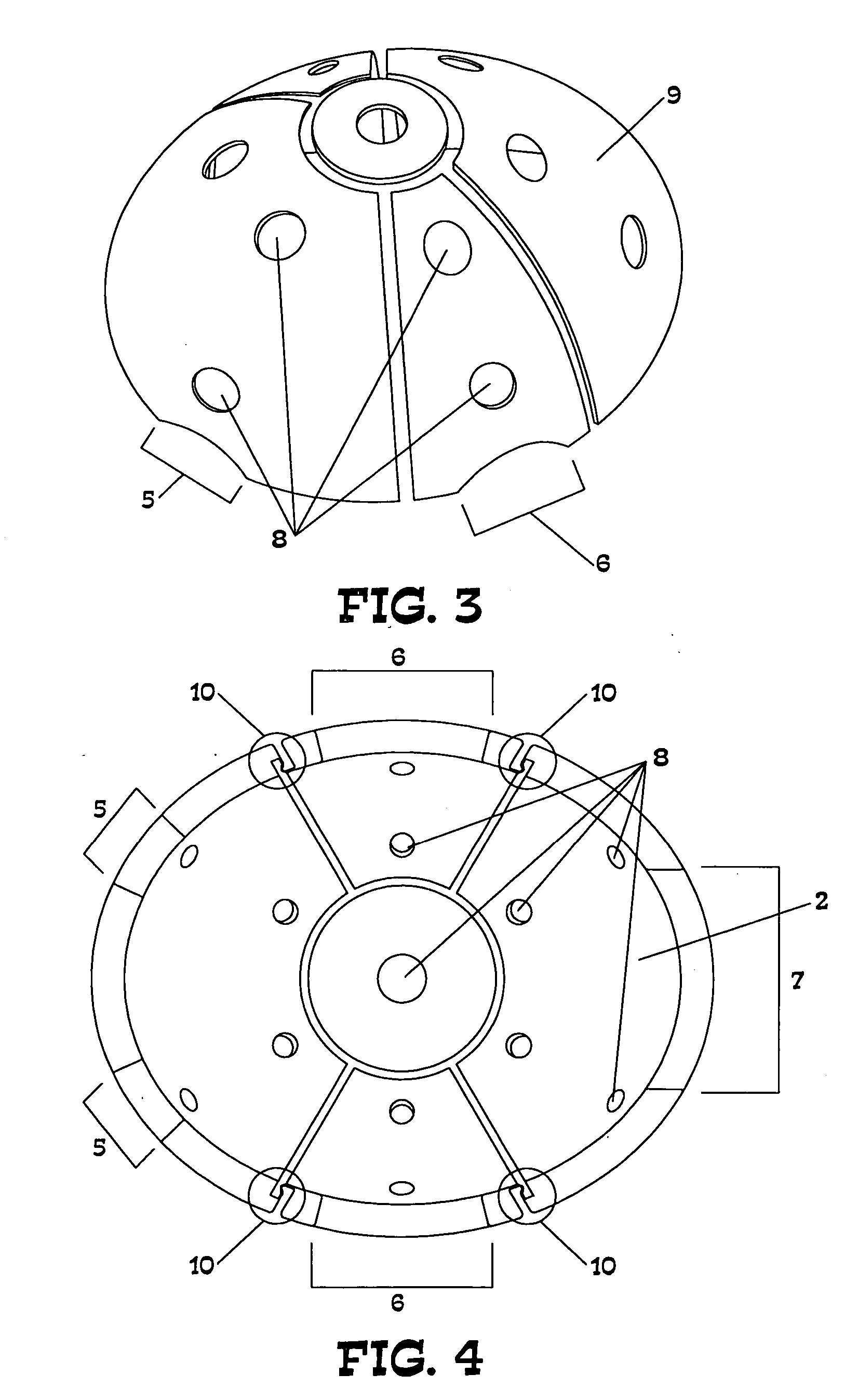
[0061]FIG. 3 is a perspective view of the rigid plates of the first embodiment of the present invention. In this embodiment, rigid plates 9 are embedded within the foam insert 2. These rigid plates are not visible in FIGS. 1 and 2. The rigid plates are preferably made of polypropylene or polycarbonate, and they contain ventilation holes 8. Although the present invention is not limited to any particular configuration of ventilation holes 8, the configuration of ventilation holes 8 on the rigid plates 9 is...

second embodiment

[0070]FIG. 9 is a perspective view of the rigid shell of the present invention without the outer covering. The cushions 12 and nozzles 14 are not visible in this figure because they are on the interior of the rigid shell. This figure does show the optional ear cutout 6. Although the rigid shell is shown without ventilation holes, it may optionally include ventilation holes.

[0071]FIG. 10 is a bottom view of a second embodiment of the present invention. This figure shows the cushions 12, rigid shell 13, and nozzles 14. This figure shows one particular array of cushions, but the present invention is not limited to any particular shape, number or array of cushions.

[0072]FIG. 11 is a partial section view of a second embodiment of the present invention. This figure shows the orientation of one of the cushions 12 on the inside of the rigid shell 13.

[0073]FIG. 12 is a section view of a second embodiment of the present invention, with additional occipital protection. This figure shows the ...


PUM


Abstract

A safety cap comprising a plurality of rigid plates, a foam insert, and an outer covering. The rigid plates are embedded within the foam insert, and the foam insert comprises foam joints. A safety cap comprising a plurality of cushions, a rigid shell, and an outer covering. The cushions are attached to the inside of the rigid shell, and they comprise a plurality of nozzles. A safety cap in which rigid plates and cushions are embedded within a foam insert. The cushions are positioned on the inner surface of the rigid plates and may contain air, foam, fluid or a combination thereof. The outer covering is preferably made of fabric, and the cap preferably comprises an adjustable strap. The cap optionally includes ventilation holes, ear cutouts, eye cutouts, a ponytail cutout, an eye protector and / or a face protector.

Description

BACKGROUND OF THE INVENTION [0001] 1. Field of the Invention. [0002] The present invention relates to the field of protective head gear. More particularly, the present invention is a universal safety cap that is intended to prevent head injuries caused by a fall, projectile, or other impact to the head. Although the present invention is not limited to any particular application, the safety cap was designed primarily to be worn by youths when playing baseball. The safety cap may be worn in connection with athletic or industrial activities or for general safety purposes (for example, it may be worn by toddlers or the elderly). [0003] 2. Description of the Related Art. [0004] A number of devices that are intended to provide protection to the head of an athlete during competition or practice have been patented or are the subject of pending patent applications. More specifically, there are several patented and “patent pending” inventions that are intended to look more like a hat than a h...

Claims


Application Information

Patent Timeline
IPC IPC(8): A42B3/00
CPCA42B1/08A42B1/247A42B3/003A42B3/062A42B3/08A42B3/12A42B3/185A42B3/28A42B7/00A42C5/04
Inventor MAZZOCCOLI, JEFF C.MAZZOCCOLI, DANA J.MAZZOCCOLI, PASQUALE DILLONMARSHALL, JULIANNEMAZZOCCOLI, JENNA ALEXANDRAALBINI, MARTINJENKS, GORDONC
Owner MAZZ ENTERPRISES
Learn More