Measuring and marking guide tool

a technology of marking guide and measuring guide, which is applied in the direction of distance measurement, circular curve drawing instruments, instruments, etc., can solve the problems of less than desirable techniques and poor accuracy

Inactive Publication Date: 2006-07-27
VICK DANIEL S
View PDF18 Cites 12 Cited by
  • Summary
  • Abstract
  • Description
  • Claims
  • Application Information

AI Technical Summary

Benefits of technology

[0006] By means of the present invention, there is provided a simplified unitary guide device or tool that provides a guide suitable for measuring and marking a work piece when moved along an edge of the work piece. The guide tool can be used with or without a retractable tape. The guide tool is in the form of an elongate, generally rectangular block or bar having an offset segment which forms a step preferably toward the end of one side for engaging the edge of a work piece in a first disposition and engaging a measuring tape dispenser housing in another disposition. The block is slidable along the edge of a work piece and has a longer dimension designed to extend generally perpendicular to an engaged edge of a work piece. The opposed sides of the guide tool are generally parallel and flat except for the offset or step.
[0007] The guide tool further can be provided with scales on one or both opposed sides including one or more series of spaced aligned holes or openings along the length of the block for use in marking the work piece with the block in the first described disposition. The tool can also be used with the flat side against the work piece to enable the user to scribe arcs with the assistance of the spaced openings along the tool. The openings can be offset different distances as measured from each end of the tool so that two different offset scales are provided.
[0008] The tool can be fabricated from any suitable material that can retain an edge. Any suitable manufacturing technique may be used. Thus, numerous plastic materials and metals such a aluminum may be used and the article may be cut from bar stock, molded or extruded. Also, while a relatively small pocket tool size is easiest to use, the guide tool of the invention may be made in any convenient size. A typical size may be about 6 inches long by 1 inch wide with a step 1 inch from one end. A typical thickness might be ¼ inch with an additional ¼ inch at the step.

Problems solved by technology

While the technique has long been used and is generally successful, it requires the user's fingers to slide along in contact with the edge of the work piece and injuries including slivers and abrasions to the fingers of the sliding hand holding the tape are common, making this technique less than desirable in that respect.
In addition, accuracy may suffer if the relationship between the tape and the work piece shifts at all during scribing.

Method used


Image

  • Measuring and marking guide tool
  • Measuring and marking guide tool
  • Measuring and marking guide tool

Examples


Embodiment Construction

[0016] The following description is directed to an example embodiment of the guide tool of the invention intended to convey the concept of the invention, but not to limit the scope of the invention in any manner. With this in mind, the embodiment illustrated in the drawing figures will next be described.

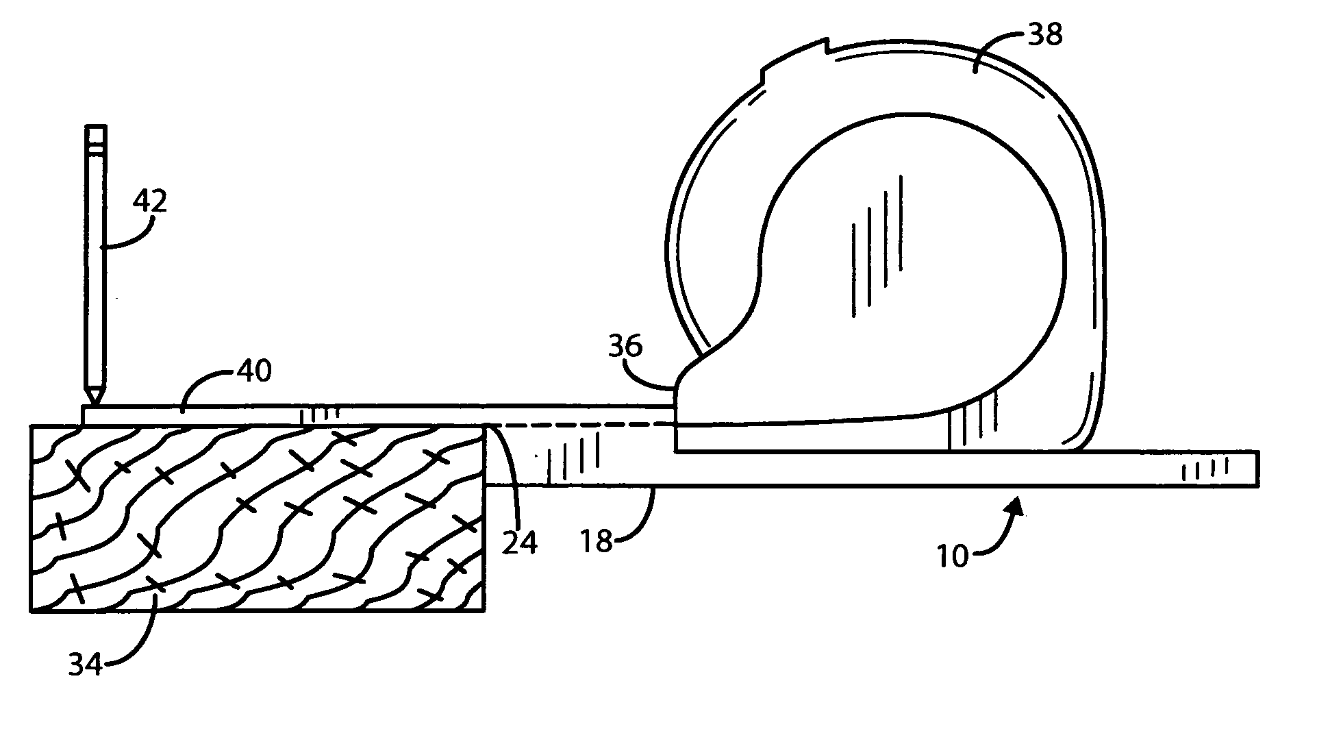
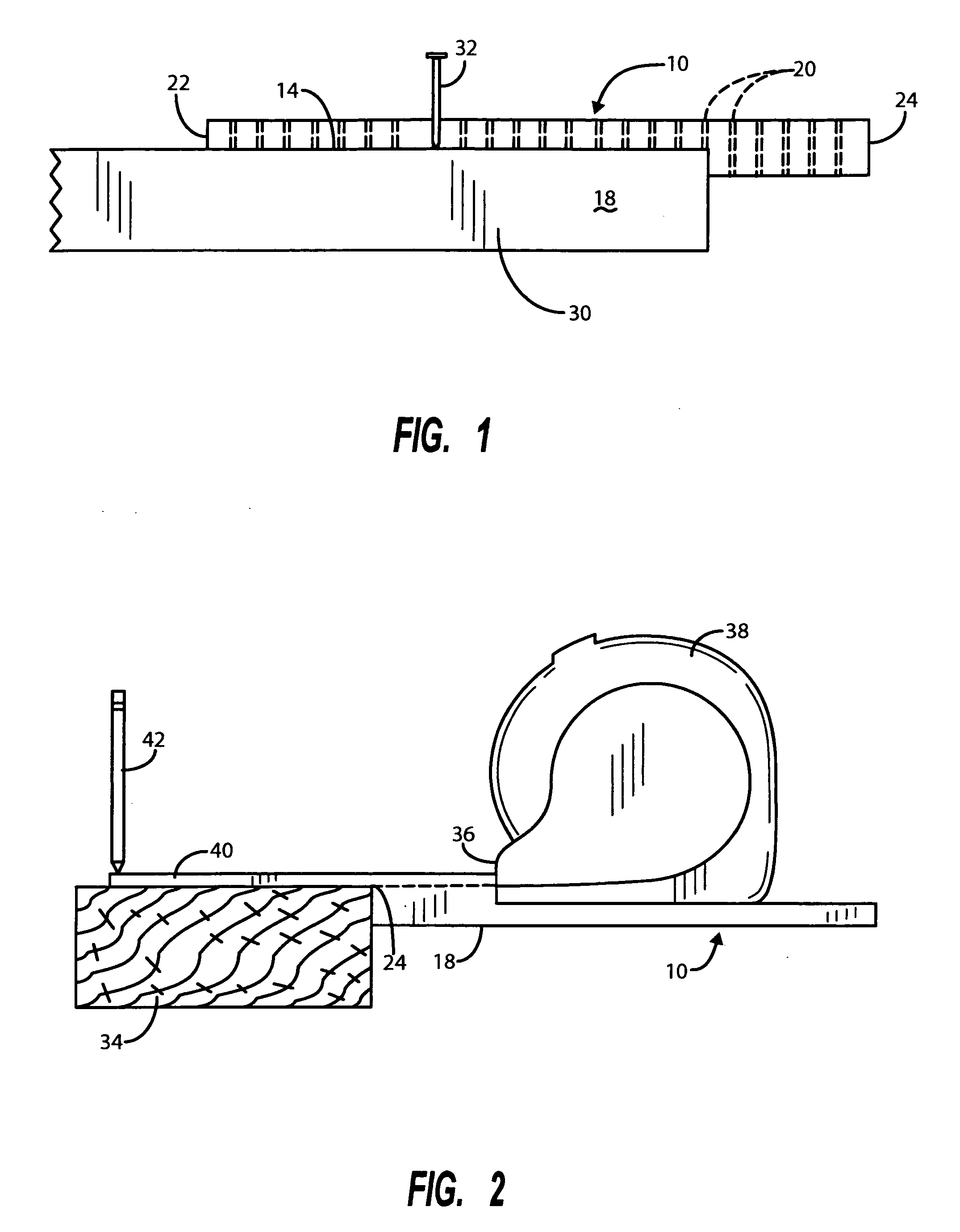
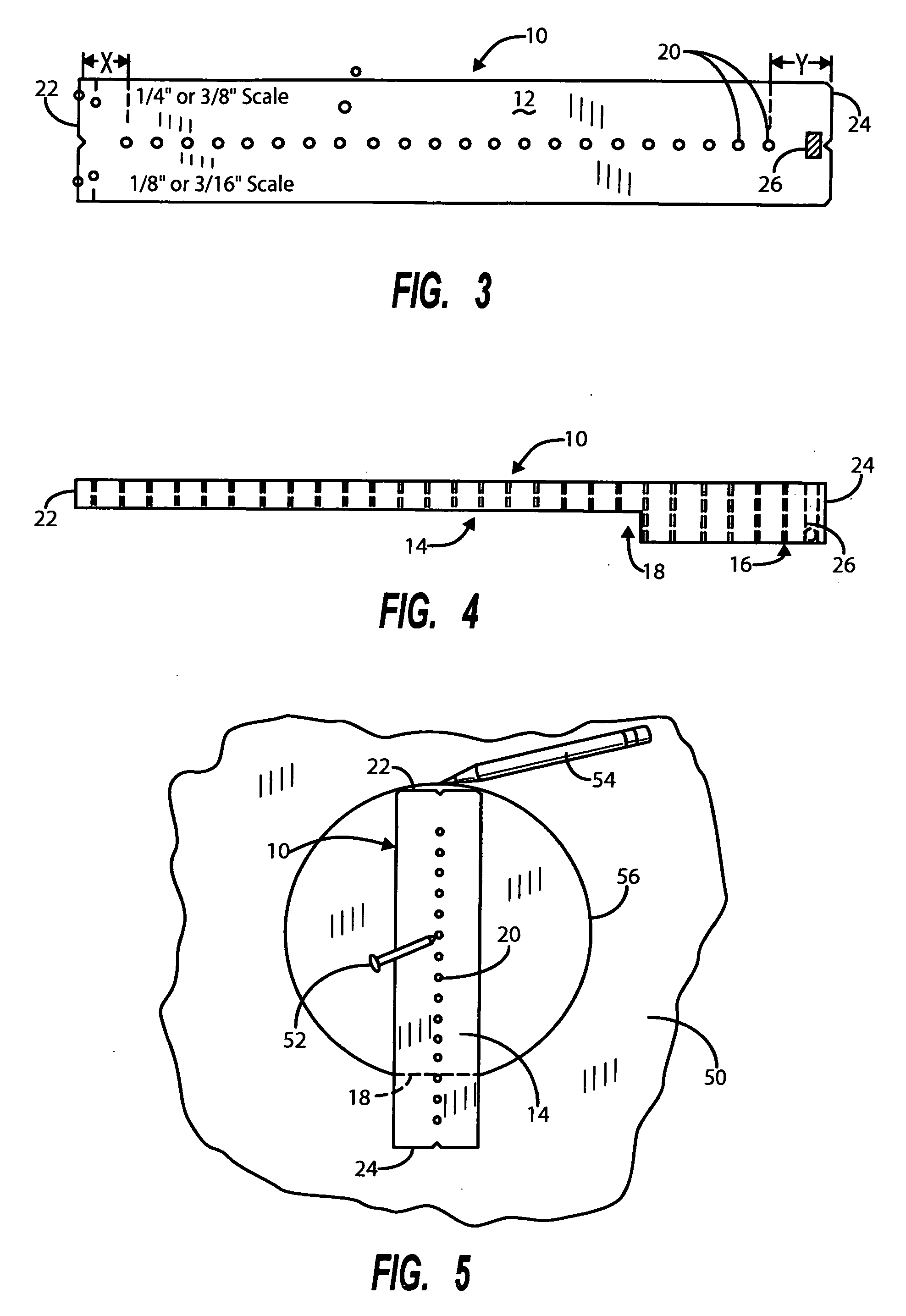
[0017]FIGS. 3 and 4 depict a top view of the flat side of the guide tool of the invention and a side elevational view, respectively. The guide tool, depicted generally by 10, is preferably in the form of a bar that is generally rectangular in shape and has a planer or flat side 12 and a stepped side 14 characterized by a thicker section 16 forming a step at 18. The tool includes a series of aligned, evenly spaced openings or holes as at 20 which extend along the length or longer dimension of the guide tool and define a scale which can be used to measure distances between the holes or openings 20 or between the holes and either end of the tool 10. Thus, for example, a series of openi...


PUM


Abstract

A unitary guide tool that provides a guide for measuring and marking a work piece when moved along an edge thereof, the guide tool being in the form of a generally rectangular offset or stepped bar of material having a thicker section forming a stepped side for engaging the edge of a work piece in a first disposition and engaging a measuring tape dispensing housing in another disposition, the block being slidable along an edge of the work piece and having a longer dimension extending generally perpendicular thereto.

Description

BACKGROUND OF THE INVENTION [0001] I. Field of the Invention [0002] The present invention relates to marking guide tools generally and, more particularly, to a one-piece multi-use marking guide tool suitable for use alone, or in conjunction with a retractable metal measuring tape, in measuring and marking a work piece; or employed with a cutting tool or other device. [0003] II. Related Art [0004] It has long been a common practice for wood workers such as carpenters or the like to scribe lines along and parallel to the edges of boards or sheets of building material such as plywood using a marker and a retractable tape or the like. The tape is grasped between fingers of one hand extended to the desired measurement location and a marking pencil or other marking tool is held against the end of the tape using the other hand and thereafter a line is scribed along the work piece by moving and following the tape along the edge of the work piece. While the technique has long been used and i...

Claims


Application Information

Patent Timeline
Patent Type & Authority Applications(United States)
IPC IPC(8): B43L13/02
CPCB25H7/04B26B29/06B43L7/005B43L9/007B43L13/02G01B2003/1089G01B2003/1092G01B3/1092G01B3/1089
Inventor VICK, DANIEL S.
Owner VICK DANIEL S
Why Eureka
Try Eureka