
User interface with displaced representation of touch area

a user interface and touch area technology, applied in the field of data processing system, can solve the problems of affecting interaction, partially or completely covering the objects around the touch, and severely disturbing the interaction of the pointing obj

Active Publication Date: 2006-07-20
KONINKLIJKE PHILIPS ELECTRONICS NV
View PDF21 Cites 260 Cited by
  • Summary
  • Abstract
  • Description
  • Claims
  • Application Information

AI Technical Summary

Benefits of technology

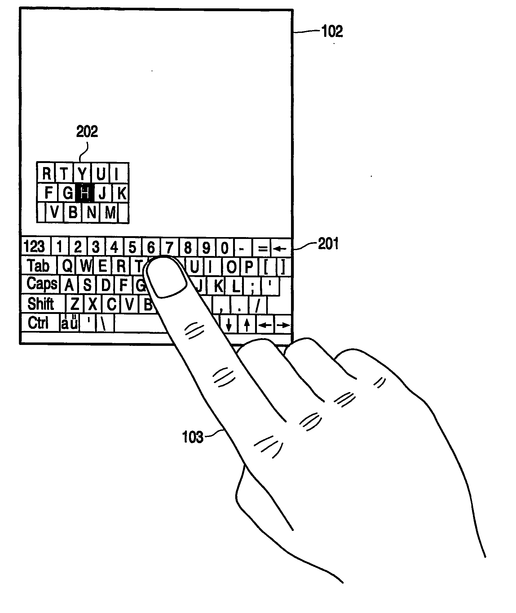
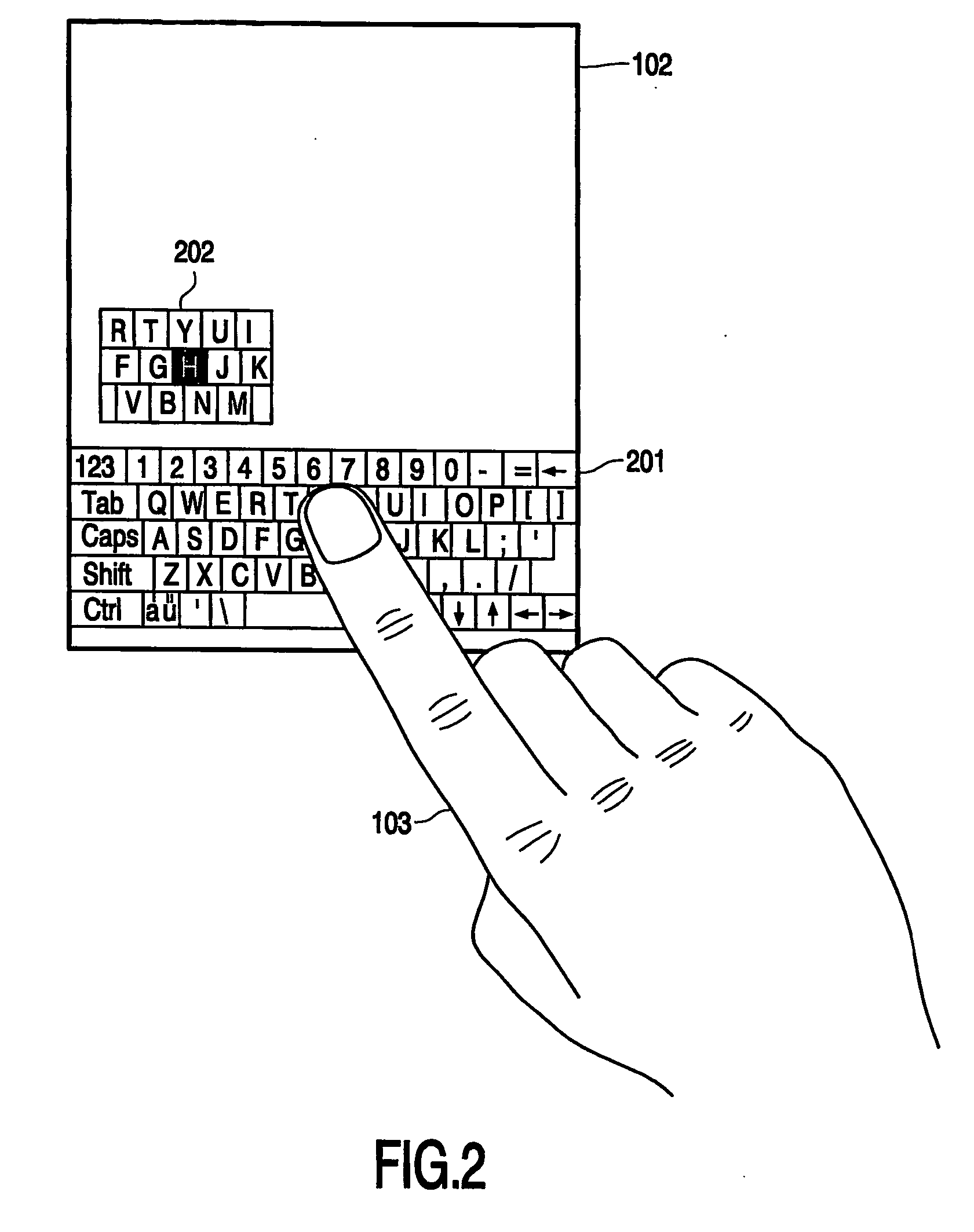
[0018] The invention is particularly suitable for portable devices such as PDA's and touch screen remote controls. However, the invention is equally well applicable to any other data processing systems, such as personal computers and notebooks, when equipped with a touch screen. A particular advantage of the present invention is that the touch area itself can remain unchanged, so confusion with the user when approaching the desired touch position is avoided. Instead, the representation of the touch area is displayed at some distance of the touch position, thus providing the user with a clear overview of the touch area without disturbing the touch area itself, e.g. by magnification. The area to be represented may be rectangular, but may equally well be circular or have any other desired shape.
is that the touch area itself can remain unchanged, so confusion with the user when approaching the desired touch position is avoided. Instead, the representation of the touch area is displayed at some distance of the touch position, thus providing the user with a clear overview of the touch area without disturbing the touch area itself, e.g. by magnification. The area to be represented may be rectangular, but may equally well be circular or have any other desired shape.

Problems solved by technology

A drawback of any touch screen based system is that, while interacting with the system, the pointing object partially or completely covers the objects around the touch position.
Especially if the pointing object is a user's finger and the objects displayed in the area around the touch position are small, this severely disturbs the interaction.

Method used


Image

  • User interface with displaced representation of touch area
  • User interface with displaced representation of touch area
  • User interface with displaced representation of touch area

Examples


Embodiment Construction

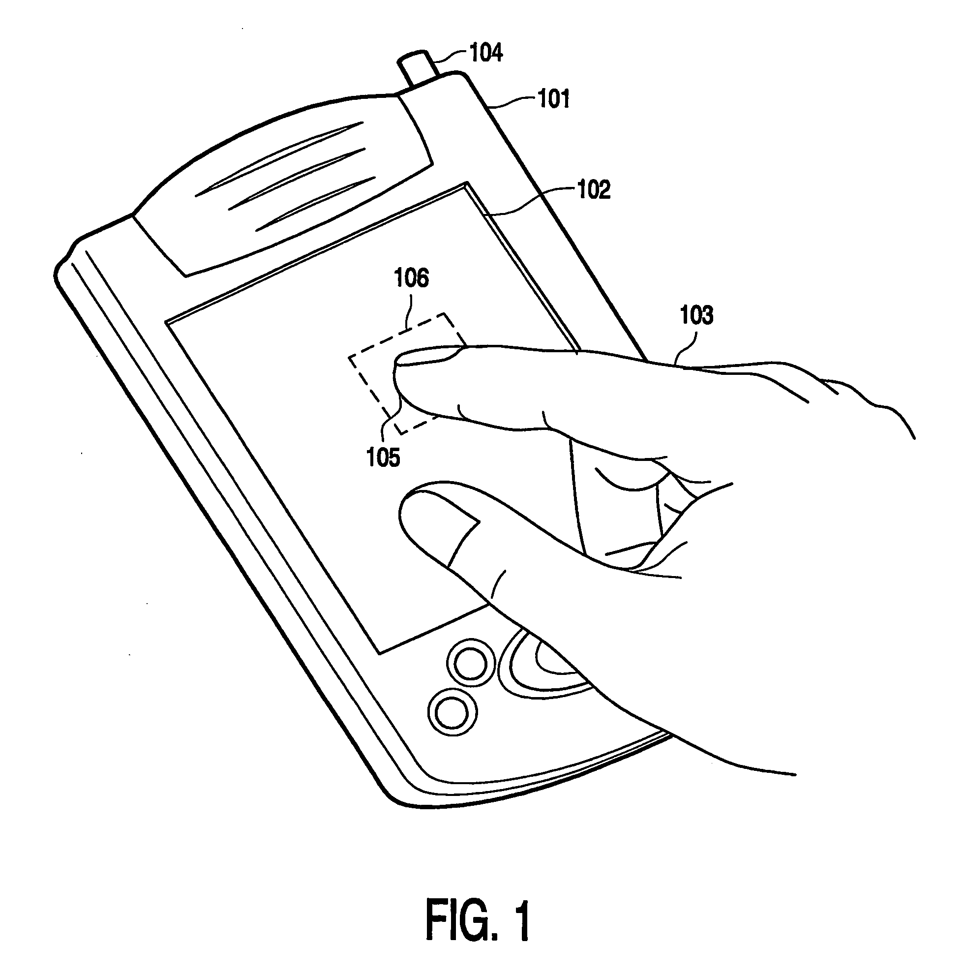
[0024] Throughout the Figures, the same reference numerals indicate similar or corresponding features. FIG. 1 shows a personal digital assistant (PDA) 101 as a data processing system embodying the invention. The PDA 101 comprises a touch sensitive display screen 102, capable of displaying objects of a graphical user interface and enabling the user to interact with an interactive application by touching the objects with his finger 103 or a dedicated stylus 104. As depicted in FIG. 1, a touch position 105 is detected by the display screen 102, which may be defined, for example, as the center of the contact area between the user's finger and the display screen. A touch area 106 is determined as an area of particular interest around the touch position, for example a number of graphical buttons which might be the target object given the width of the pointing object. If the pointing object is the user's finger, the touch area 106 may be chosen to be relatively large, whereas if the pointi...


PUM


Abstract

The invention relates to a data processing system comprising a display screen (102), a graphical user interface for displaying objects on the display screen, and detection means (102) for detecting a touch position of a pointing object (103) on the display screen. The detection means (102) is capable of measuring a distance between the pointing object and the display screen. A property of the displayed objects is dependent on the measured distance between the pointing object and the display screen.

Description

FIELD OF THE INVENTION [0001] The invention relates to a data processing system comprising a display screen, a graphical user interface for displaying objects on the display screen, and detection means for detecting a touch position of a pointing object on the display screen. [0002] The invention further relates to a method of enabling a user to interact with a data processing system, the method comprising a step of displaying objects on a display screen, and a step of detecting a touch position of a pointing object on the display screen. [0003] The invention further relates to a computer program product for performing the steps of the above method. BACKGROUND OF THE INVENTION [0004] Touch screens are widely applied today. The best known example of such a data processing system is the personal digital assistant (PDA) which is a compact personal computer providing a graphical screen for displaying objects of a graphical user interface, such as text strings and hyperlinks, graphical b...

Claims


Application Information

Patent Timeline
IPC IPC(8): G09G5/08G06FG06F1/00G06F3/0484G06F3/0488
CPCG06F3/04842G06F3/04886G06F2203/04805G06F3/0233G06F3/0484G06F3/0488
Inventor VAN LEEUWEN, MARCO
Owner KONINKLIJKE PHILIPS ELECTRONICS NV
Learn More