
Virtual retinal display generating principal virtual image of object and auxiliary virtual image for additional function

a retinal display and principal virtual image technology, applied in the field of virtual retinal displays, can solve the problems of relative difficulty in precisely interpreting the absolute size of the display object and the distance of the display object from the viewer, and achieve the effect of reducing viewer fatigue and stable perception

Inactive Publication Date: 2006-07-06
BROTHER KOGYO KK
View PDF2 Cites 18 Cited by
  • Summary
  • Abstract
  • Description
  • Claims
  • Application Information

AI Technical Summary

Benefits of technology

[0012] For any one of the above types, an apparatus for displaying an image is required to reduce fatigue of a viewer while perceiving a display object, and to achieve stable perception by the viewer of the display object. What is important for satisfying such requirements is to allow the viewer to perceive or interpret an absolute size of the display object and a distance of the display object image from the viewer, as correctly as possible, through a corresponding virtual image.
[0013] The employment of a conventional image display of enclosed type described above, however, causes a viewer to perceive a virtual image solely, without allowing the viewer to rely on a real world scene which contains a real existence separate from the virtual image. The real existence can be a clue or a cue (i.e., a visual presentation) which can promote true perception by the viewer of the absolute size of the display object (i.e., its virtual image) and the distance of the display object (i.e., its virtual image) from the viewer.

Problems solved by technology

The employment of a conventional image display of enclosed type described above, however, causes a viewer to perceive a virtual image solely, without allowing the viewer to rely on a real world scene which contains a real existence separate from the virtual image.
For this reason, the viewer, when using this conventional enclosed display, finds it relatively difficult to precisely interpret the absolute size of the display object and the distance of the display object from the viewer.

Method used


Image

  • Virtual retinal display generating principal virtual image of object and auxiliary virtual image for additional function
  • Virtual retinal display generating principal virtual image of object and auxiliary virtual image for additional function
  • Virtual retinal display generating principal virtual image of object and auxiliary virtual image for additional function

Examples


first embodiment

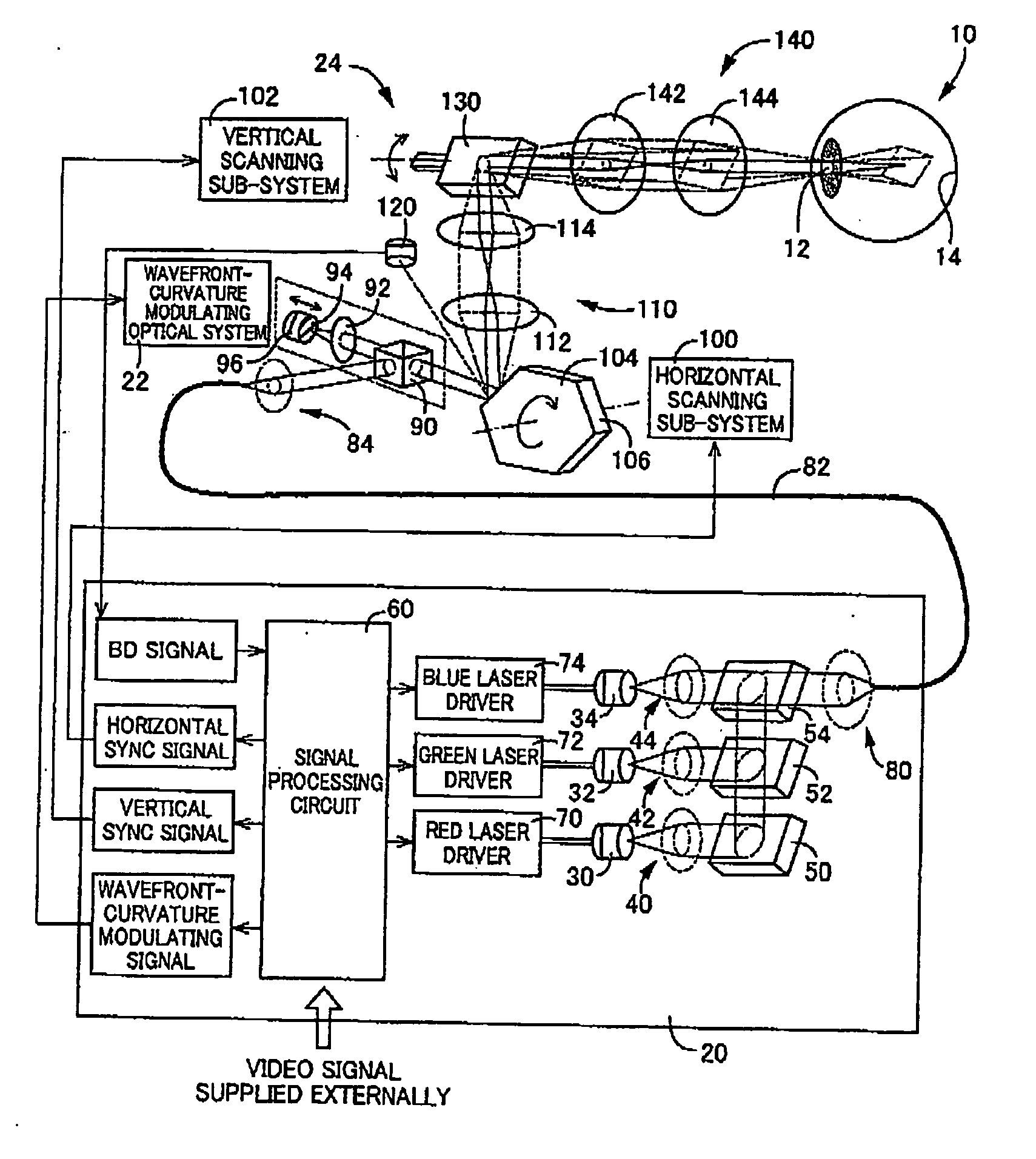
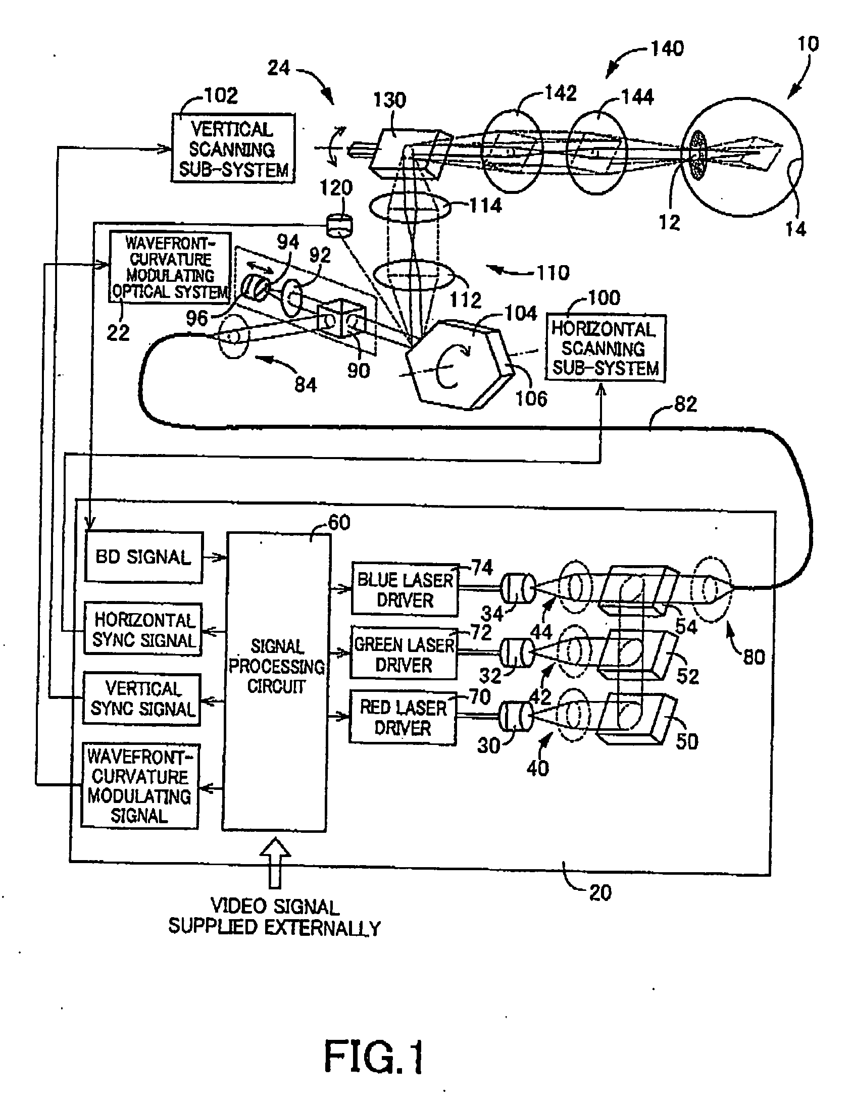
[0139] Referring now to FIG. 1, a retinal-scanning-type display device (hereinafter, abbreviated as “RSD”) according to the present invention is systematically illustrated. This RSD is an image display device of a type that projects light defining a display object through a pupil 12 of a viewer's eye 10 onto a retina 14 of the viewer, to thereby allow the viewer to perceive the display object via a virtual image.

[0140] More specifically, this RSD is configured, such that a laser beam, while it is necessarily modulated in the curvature of wavefront and the intensity of the laser beam, impinges onto an image plane on the retina 14 through the pupil 12, and such that the laser beam incident on the retinal image plane is two-dimensionally scanned thereon, whereby the laser beam defining a desired image is directly projected onto the retina 14.

[0141] That is to say, in the present embodiment, this RSD constitutes an example of the “apparatus” according to the above mode (1), and the las...

second embodiment

[0205] Next, an RSD constructed according to the present invention will be described.

[0206] The present embodiment is in common to the first embodiment concerning many elements, and is different from the first embodiment only concerning the elements relating to the presentation of an auxiliary virtual image data.

[0207] In view of that, while the common elements of the present embodiment will be referenced the same reference numerals or names as those in the description and illustration of the first embodiment, without redundant description or illustration, the different elements of the present embodiment will be described below in greater detail.

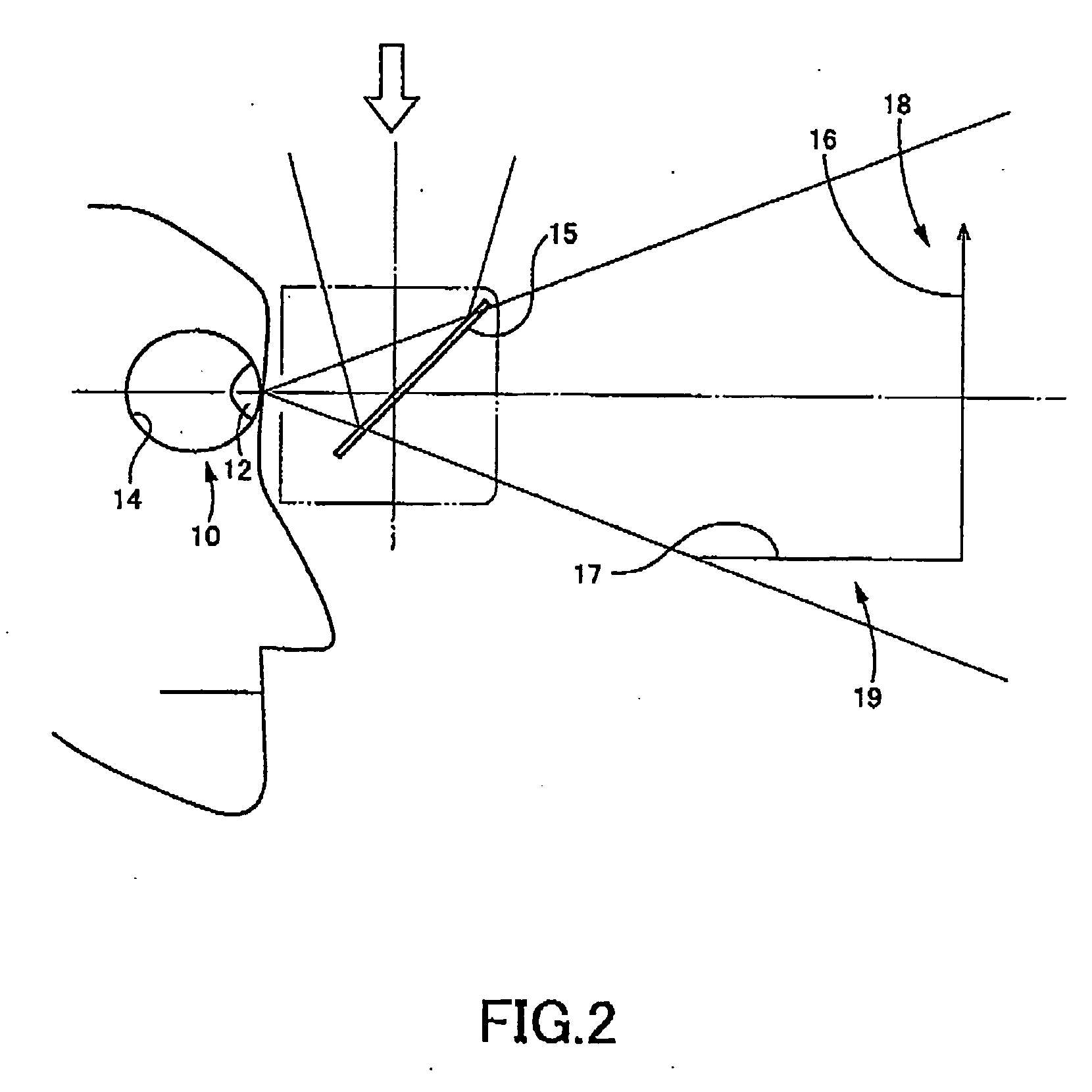
[0208] In the first embodiment, the auxiliary virtual image 17 is in the form of a perspective linear pattern, to thereby support the viewer in correctly perceiving the distance and the size of the principal virtual image 16.

[0209] Instead, the present embodiment employs, as illustrated in FIG. 6, an auxiliary virtual image 190 in the for...

third embodiment

[0219] Next, an RSD constructed according to the present invention will be described.

[0220] The present embodiment is common to the first embodiment concerning many elements, and is different from the first embodiment only concerning the elements relating to the acquisition of an auxiliary virtual image.

[0221] In view of that, while the common elements of the present embodiment will be referenced the same reference numerals or names as those in the description and illustration of the first embodiment, without redundant description or illustration, the different elements of the present embodiment will be described below in greater detail.

[0222] The RSD according to the first embodiment is configured, for allowing the viewer to perceive the auxiliary virtual image 17, such that the original auxiliary virtual image data has been previously stored in the ROM 164, and is edited as desired for application. Therefore, the presentation of the auxiliary virtual image 17 does not require an...


PUM


Abstract

An apparatus for projecting modulated light onto a retina of a viewer, to thereby allow the viewer to perceive a display object via a virtual image is disclosed. The apparatus is configured to include: an emitter emitting light; a modulator modulating the light; and a controller controlling the emitter and the modulator for generating virtual images to be perceived by the viewer in an image display field. The controller is operated, such that a principal virtual image defining the display object is perceived by the viewer in a principal display region of the image display field, and such that an auxiliary virtual image is perceived by the viewer together with the principal virtual image, in an auxiliary display region which is located in the image display field in a predetermined positional relationship with the principal display region, as viewed from the viewer.

Description

CROSS-REFERENCE TO RELATED APPLICATIONS [0001] This application is based on Japanese Patent Application No. 2003-319274 filed Sep. 11, 2003, and PCT International Application No. PCT / JP2004 / 010606 filed Jul. 26, 2004, the contents of which are incorporated hereinto by reference. [0002] This is a continuation of International Application No. PCT / JP2004 / 010606 filed Jul. 26, 2004, which was published in Japanese under PCT Article 21(2).BACKGROUND OF THE INVENTION [0003] 1. Field of the Invention [0004] The invention relates to techniques of projecting modulated light onto the retina of a viewer, to thereby allow the viewer to perceive a display object via a virtual image, and more particularly to improved techniques of generating virtual images. [0005] 2. Description of the Related Art [0006] There are known apparatuses for use in the display of an image with a wider field of view in spite of these apparatuses' compactness. The apparatuses each are configured to project modulated ligh...

Claims


Application Information

Patent Timeline
IPC IPC(8): H04N13/04H04N15/00G02B26/06G02B27/01G02B27/02G09G3/00G09G3/02G09G3/20H04N3/08H04N5/66
CPCG02B27/017G09G3/00H04N3/08
Inventor YAMADA, SHOJI
Owner BROTHER KOGYO KK
Learn More