
Hose reel

a hose and reel technology, applied in the direction of transportation and packaging, thin material processing, filament handling, etc., can solve the problems of high inconvenient, high labor intensity, and messy coiling of hose around the winding drum, and achieve the effect of simple structure, convenience and ease of us

Inactive Publication Date: 2006-07-06
LEGACY MFG
View PDF15 Cites 22 Cited by
  • Summary
  • Abstract
  • Description
  • Claims
  • Application Information

AI Technical Summary

Benefits of technology

[0004] The present utility model aims to solve technical problems by providing a hose reel that coils hose neatly, that is convenient and easy to use, and that has a simple structure.
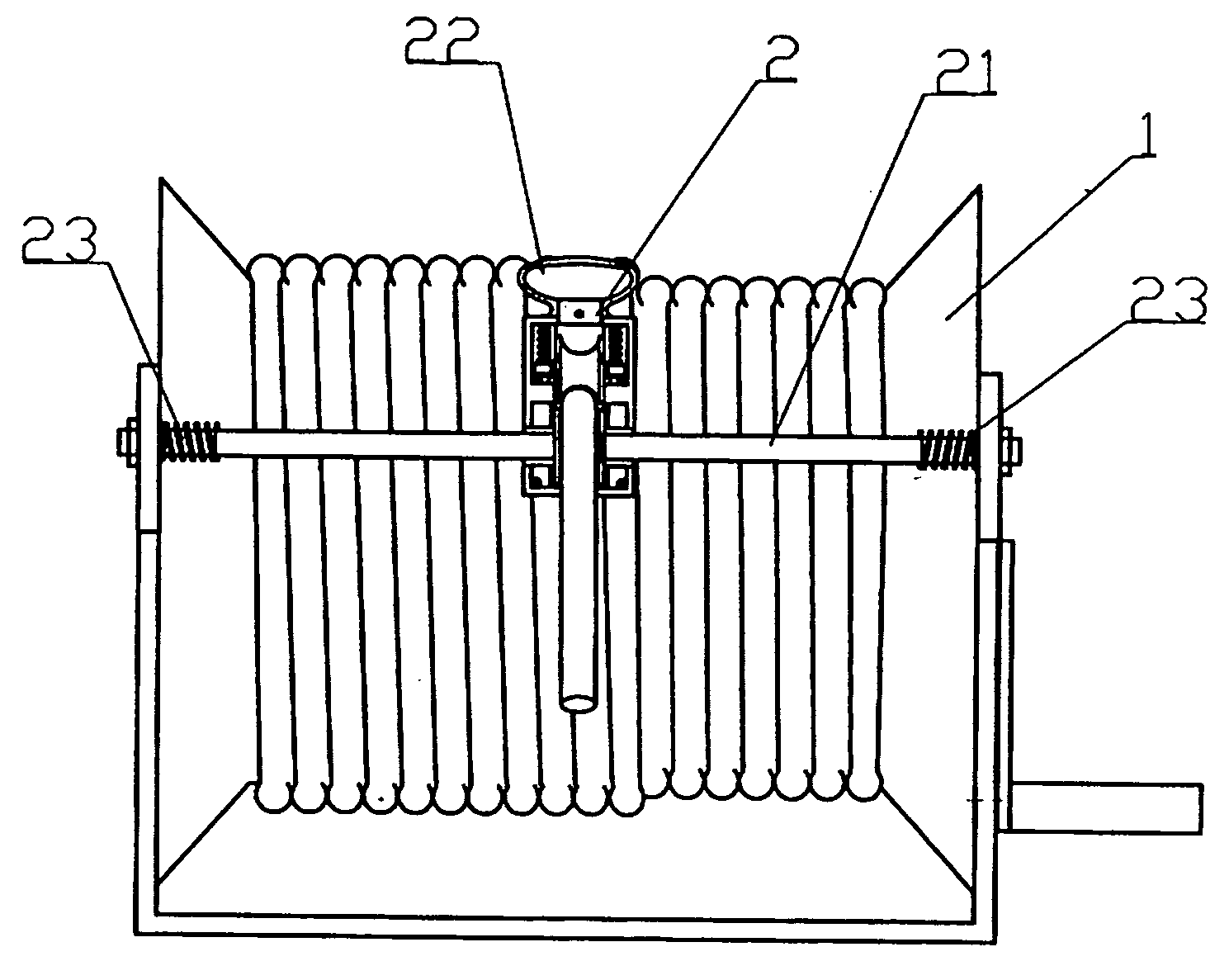
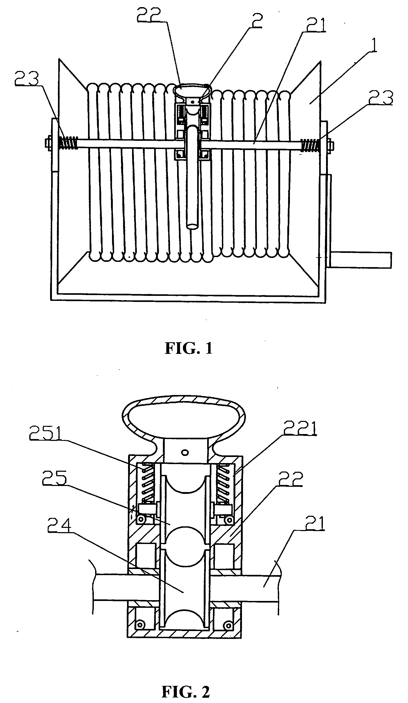
[0008] When the hose is coiled to the very end of the winding drum, the positioning unit, under the lateral force of the hose, compresses the spring on the guide rod. This causes a recovery action in the spring, moving the positioning unit in the other direction and thus guiding the hose to coil in the other direction. Therefore, one needs only to rotate the winding drum, and the hose, under its own lateral force and the guiding action of the guide rod, will coil neatly and in the proper order. It is convenient and easy to use.
[0012] Thus, by means of rolling friction of this sort, the friction between the hose and the positioning unit is reduced, and damage to the hose is prevented. Furthermore, the hose can be drawn out or coiled with greater ease.
[0019] Thus, by means of this position-limiting spring, it is possible to adjust the gap between the first guide wheel and the second guide wheel.
[0021] To summarize the above, the present utility model is superior to the current art in the following ways: A positioning device is mounted on a hose reel. By rotating the winding drum, one can cause the hose to coil sequentially on the winding reel. It is characterized by neat and orderly coiling of the hose, convenience and ease of use, and simplicity of structure.

Problems solved by technology

When the hose is coiled by turning the winding drum, the coil of hose around the winding drum becomes very messy.
Thus, the act of coiling requires much effort and is highly inconvenient.

Method used


Image

  • Hose reel
  • Hose reel

Examples


Embodiment Construction

[0024] With reference to FIG. 1, a hose reel includes a winding drum 1 and a support. The winding drum 1 is mounted on the support. A hose is coiled around the winding drum 1. The hose reel further comprises a positioning assembly 2 that includes a guide rod 21, a positioning unit 22, and two springs 23. The positioning unit 22 is slidably mounted on the guide rod 21. The two ends of the guide rod 21 rest on the support. The two springs 23 fit over the guide rod 21 and are separately disposed on two sides of the positioning unit 22. The positioning unit 22 has a hose hole. The hose passes out through this hose hole. When the winding drum 1 is rotated to coil the hose, the hose that wraps around the winding drum 1 exerts a lateral force on the hose hole in the positioning unit 22, causing the hose that is being coiled around the winding drum 1 to be coiled sequentially. In addition, the positioning unit 22 guides the hose along the guide rod 21. When the hose is coiled to the very en...


PUM


Abstract

The present utility model relates to winding devices for guiding or ensuring the sequential coiling of steel cables or chains. In particular, it relates to a reel for hoses. It comprises a winding drum and a support. The winding drum is mounted on the support, and a hose is coiled around the winding drum. Its main structural elements: It further comprises a positioning assembly. The positioning assembly comprises a guide rod, a positioning unit, and two springs. The positioning unit is slidably mounted on the guide rod, and the two ends of the guide rod rest on the support. The two springs fit over the guide rod and are separately disposed on two sides of the positioning unit. The positioning unit has a hose hole, and the hose passes out through this hose hole. When the winding drum is rotated, the positioning assembly mounted on the hose reel can cause the hose to coil sequentially on the winding drum. It is characterized by neat and orderly coiling of the hose, convenience and ease of use, and simplicity of structure.

Description

CROSS-REFERENCE TO RELATED APPLICATION [0001] This application claims the benefit of related Chinese Application No. 200420055077.0, filed on Dec. 22, 2004. FIELD OF INVENTION [0002] The present utility model relates to winding devices that guide or ensure sequential coiling of steel cables or chains. In particular, it relates to a reel for hoses. BACKGROUND [0003] In the current art, a hose reel comprises a winding drum around which a hose is coiled. When the hose is coiled by turning the winding drum, the coil of hose around the winding drum becomes very messy. If one wants to arrange the hose neatly, one needs to manually put the hose in sequential order. During this procedure, one hand turns the winding drum, and the other hand holds the hose to put it in sequential order. Thus, the act of coiling requires much effort and is highly inconvenient. SUMMARY OF INVENTION [0004] The present utility model aims to solve technical problems by providing a hose reel that coils hose neatly,...

Claims


Application Information

Patent Timeline
Patent Type & Authority Applications(United States)
IPC IPC(8): B65H75/44
CPCB65H75/4405B65H2701/33
Inventor TSAI, CHIENFANG
Owner LEGACY MFG
Learn More