
Aggregate handling system

a technology of handling system and aggregate, which is applied in the direction of mixers, weighing apparatus, weighing equipment, etc., can solve the problems of aggregate delivery, storage, weight and transfer of aggregate in the current concrete batching plant, and pollution of the plant and surrounding area

Active Publication Date: 2006-06-01
INTRAY CONSOL
View PDF8 Cites 15 Cited by
  • Summary
  • Abstract
  • Description
  • Claims
  • Application Information

AI Technical Summary

Benefits of technology

"The present invention provides an aggregate handling system that includes an aggregate delivery station and storage apparatus for receiving and weighing aggregate from a delivery truck. The system also includes a conveyor for transferring the aggregate to a batching area. The delivery bays are located at ground level, and the storage apparatus, weigh apparatus, and conveyor are all located below ground level. The delivery bays have a floor with openings that allow aggregate to pass through while a delivery truck passes over the floor. The floor also has longitudinal members and positioning members for receiving the longitudinal members. The system also includes a wall that divides adjacent delivery bays. The technical effects of the invention include improved efficiency in handling aggregate and reduced labor costs."

Problems solved by technology

Wind can disperse fine particulate matter, polluting both the plant and surrounding area.
However, loaders are still required to transport the aggregate from the bin to the overhead storage hopper.
The aggregate delivery, storage, weigh and transfer of aggregate in current concrete batching plants is complex, and installation and maintenance costs are high.
The storage hoppers must be constantly replenished, with use of the loaders creating traffic hazards to plant employees.
Common in all batching plants are the problems associated with dust and noise emissions.

Method used


Image

  • Aggregate handling system
  • Aggregate handling system
  • Aggregate handling system

Examples


Embodiment Construction

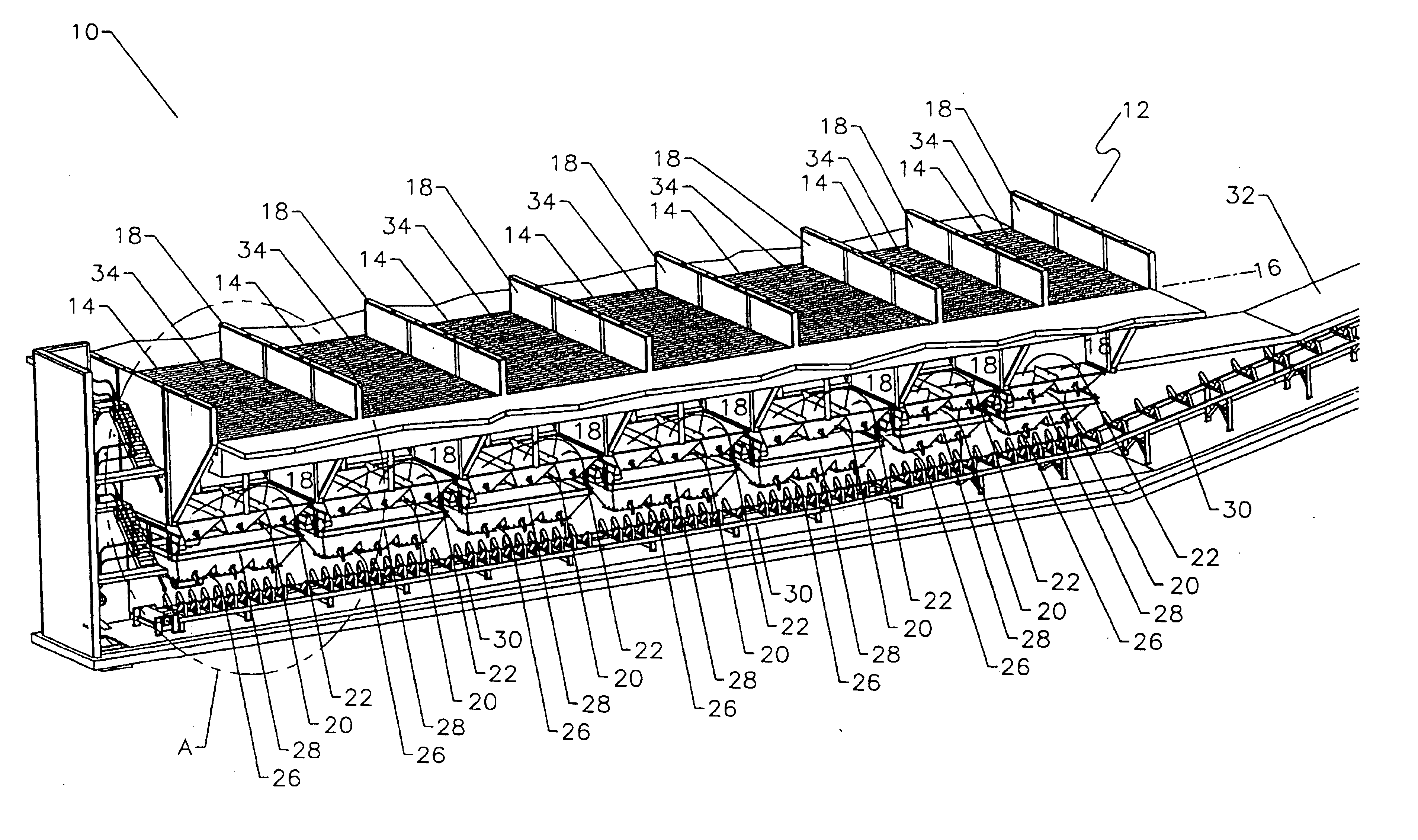
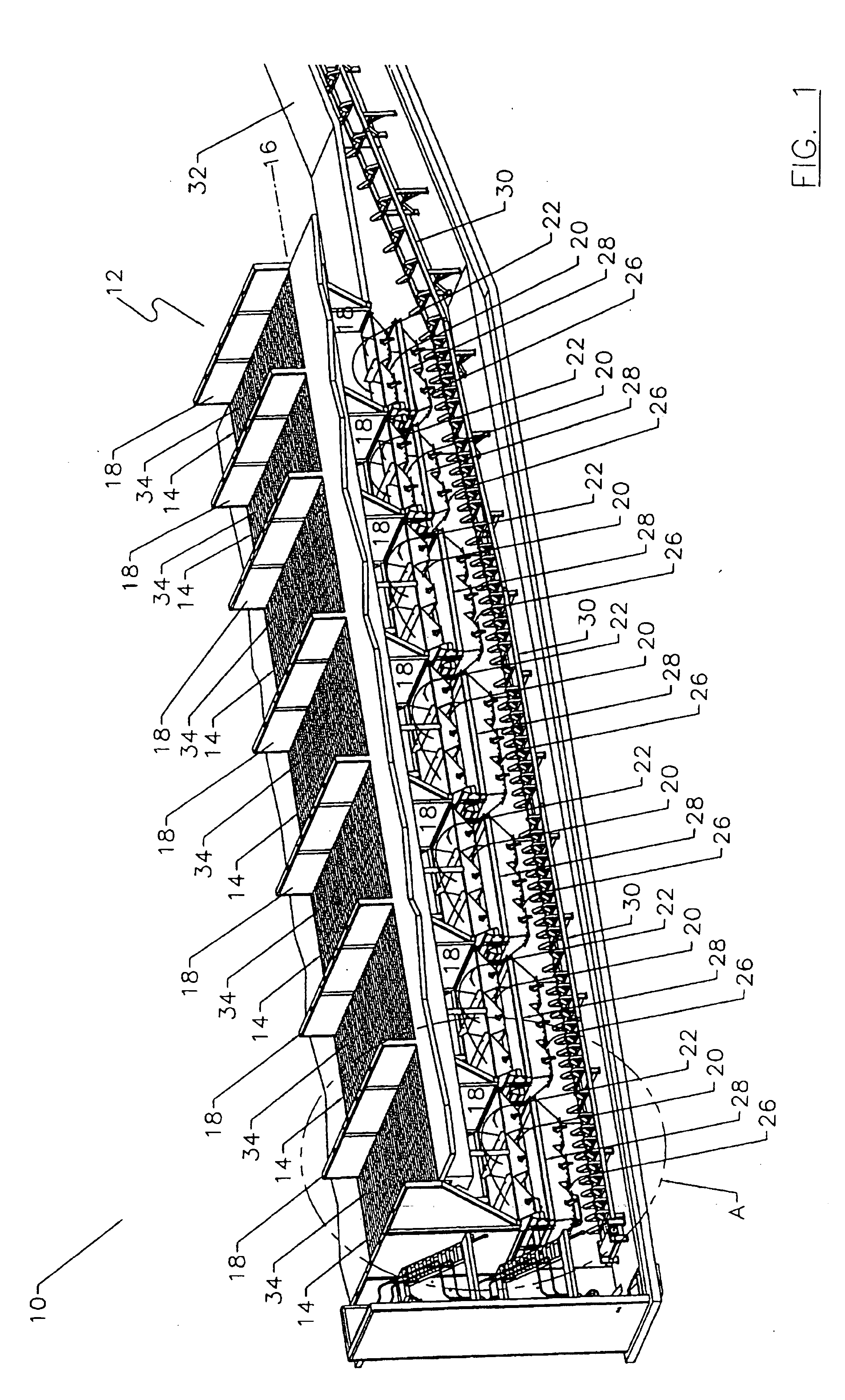
[0019] An aggregate handling system 10 is illustrated and includes an aggregate delivery station 12 including one or more delivery bays 14 for receiving aggregate from a delivery truck (not shown). In the delivery station 12 illustrated in FIG. 1 there are seven delivery bays 14, however there may be any number and each may be used to deliver a different sort of aggregate, such as sand or gravel. Delivery bays 14 are preferably located at ground level 16. Adjacent delivery bays 14 are divided by a wall 18, and are dimensioned so that a delivery truck may drive through each delivery bay 14.

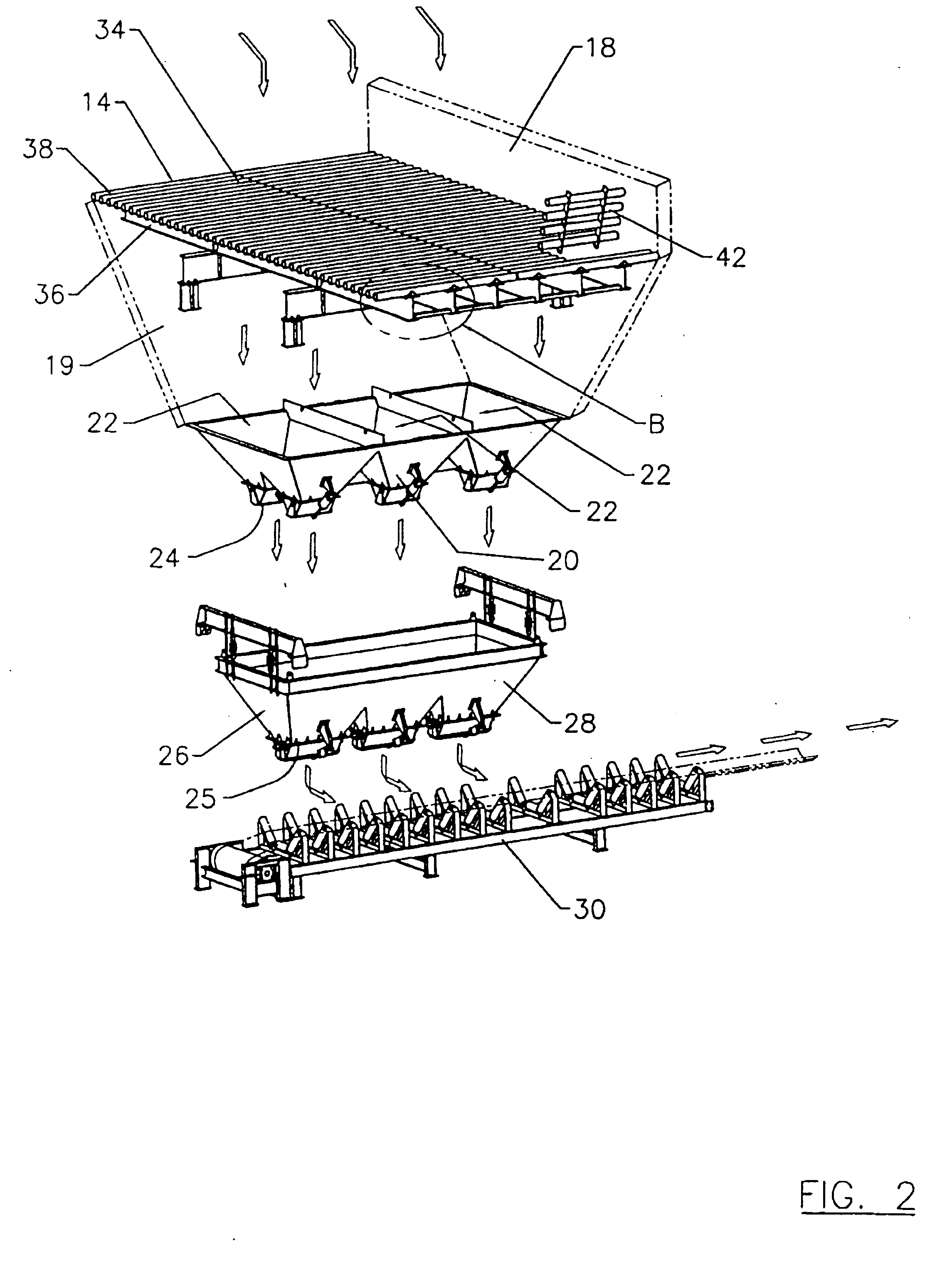
[0020] System 10 includes storage apparatus 20 associated with each delivery bay 14, best shown in FIG. 2, and adapted to receive aggregate by gravity feeding from that delivery bay 14. Each storage apparatus 20 includes one or more storage hoppers 22. Illustrated in FIG. 2 are three storage hoppers 22, however, as can be seen in FIG. 1, any number of storage hoppers 22 may be included in each sto...


PUM

PropertyMeasurementUnit
areaaaaaaaaaaa
gravityaaaaaaaaaa
noise emissionsaaaaaaaaaa

Abstract

An aggregate handling system includes an aggregate delivery station, which includes one or more delivery bays for receiving aggregate from a delivery truck. The system includes storage apparatus associated with each delivery bay and adapted to receive aggregate by gravity feeding from that delivery bay, wherein each storage apparatus includes one or more storage hoppers. The system also includes weigh apparatus associated with each storage apparatus and adapted to receive aggregate from that storage apparatus, wherein each weigh apparatus includes one or more weigh hoppers, and a conveyor for receiving aggregate from the weigh apparatus and being adapted to transfer aggregate to a batching area.

Description

FIELD OF THE INVENTION [0001] The present invention relates to aggregate handling systems. Particularly, the present invention relates to aggregate for use in batching plants, such as concrete. BACKGROUND OF THE INVENTION [0002] Concrete batching plants must adhere to strict statutory requirements regarding the control of environmental conditions. One area that requires particular attention is the delivery, storage, weigh and transfer of aggregate, such as sand and gravel. [0003] Aggregate is typically stored in storage bins. A loader, such as a front end loader, is used to periodically transport aggregate from the bin to an overhead storage hopper. A weigh hopper is generally situated directly below the storage hopper. A weighed amount of aggregate is gravity fed from the storage hopper into the weigh hopper and then transferred to a batching area. [0004] The aggregate storage bins are situated at ground level, and are enclosed on three sides to shield the aggregate from wind. Howe...

Claims


Application Information

Patent Timeline
Patent Type & Authority Applications(United States)
IPC IPC(8): B28C7/04
CPCB28C7/0436B28C7/0481G01G13/02
Inventor GALIJAN, MICHAEL N.
Owner INTRAY CONSOL
Learn More