
Methods and apparatus for transmitting signals through network elements for classification

Inactive Publication Date: 2006-05-25
GOOGLE LLC
View PDF22 Cites 85 Cited by
  • Summary
  • Abstract
  • Description
  • Claims
  • Application Information

AI Technical Summary

Benefits of technology

[0019] The present invention relates to the transmission of signals through a network of classifier elements and, more particularly, to the generation of a response or action that is based on functionally related representations of attributes of an input space and is independent of non-functionally related attributes. This is referred to as the “coherent substrate response.” The present invention provides techniques that establish functional relationships among classifiers in a network. The embodiments of the invention also introduce a novel “function / membership” classifier that enables highly efficient establishment of functional relationships across a network.
[0023] Further advantages include the enablement of the formation of consistent subsets of classifiers (classification sub-networks) subject to the constraints imposed by the network designer or a self-organizing process. The embodiments of the present invention also enable competition among self-consistent classification sub-networks, which can be used to form the basis of the classification network output or response.

Problems solved by technology

Such hierarchical networks of classifiers, however, have a fundamental limitation.
When two objects are presented to the network, however, an erroneous response can occur.
In particular, when a triangle is present in the top of the image and a square is present in the bottom, both attributes required for the behavior will be simultaneously present and the behavior will erroneously take place.
. . has no flexible means of constructing higher-level symbols by combining more elementary symbols,” and that “coactivating the elementary symbols leads to binding ambiguity when more than one composite symbol is to be expressed.”
Since there is no means to interact with the natural scene, it is not possible to pan a camera across the scene to translate the pixel information for location constrained classification.
Furthermore, since the network is fixed, it is not possible to use indirect addressing in a computer with random access memory to perform operations, such as convolutions.

Method used


Image

  • Methods and apparatus for transmitting signals through network elements for classification
  • Methods and apparatus for transmitting signals through network elements for classification
  • Methods and apparatus for transmitting signals through network elements for classification

Examples


first embodiment

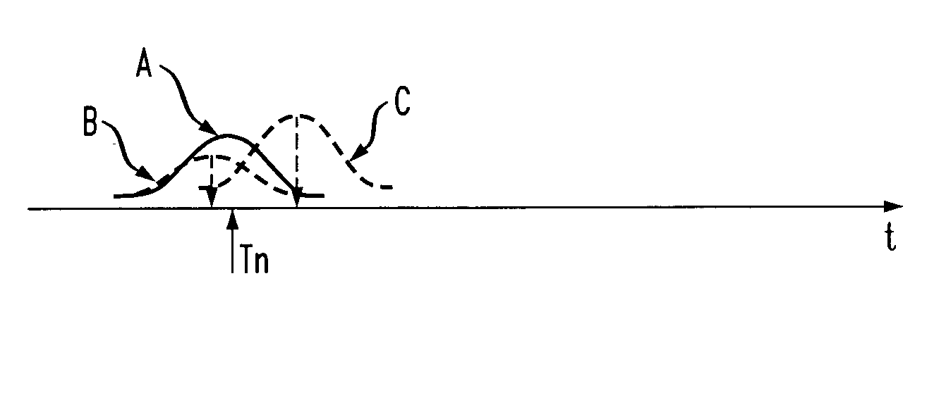
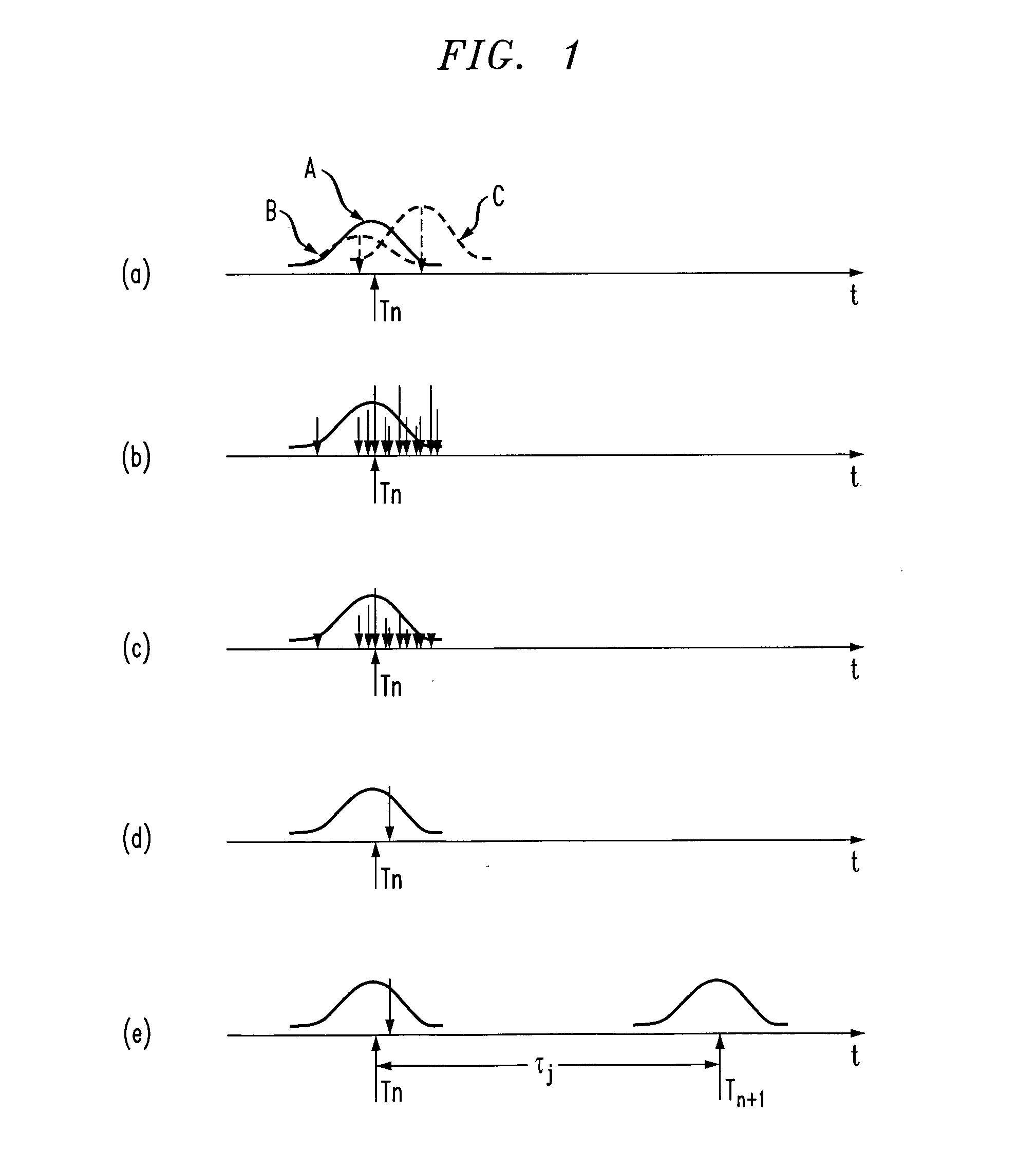
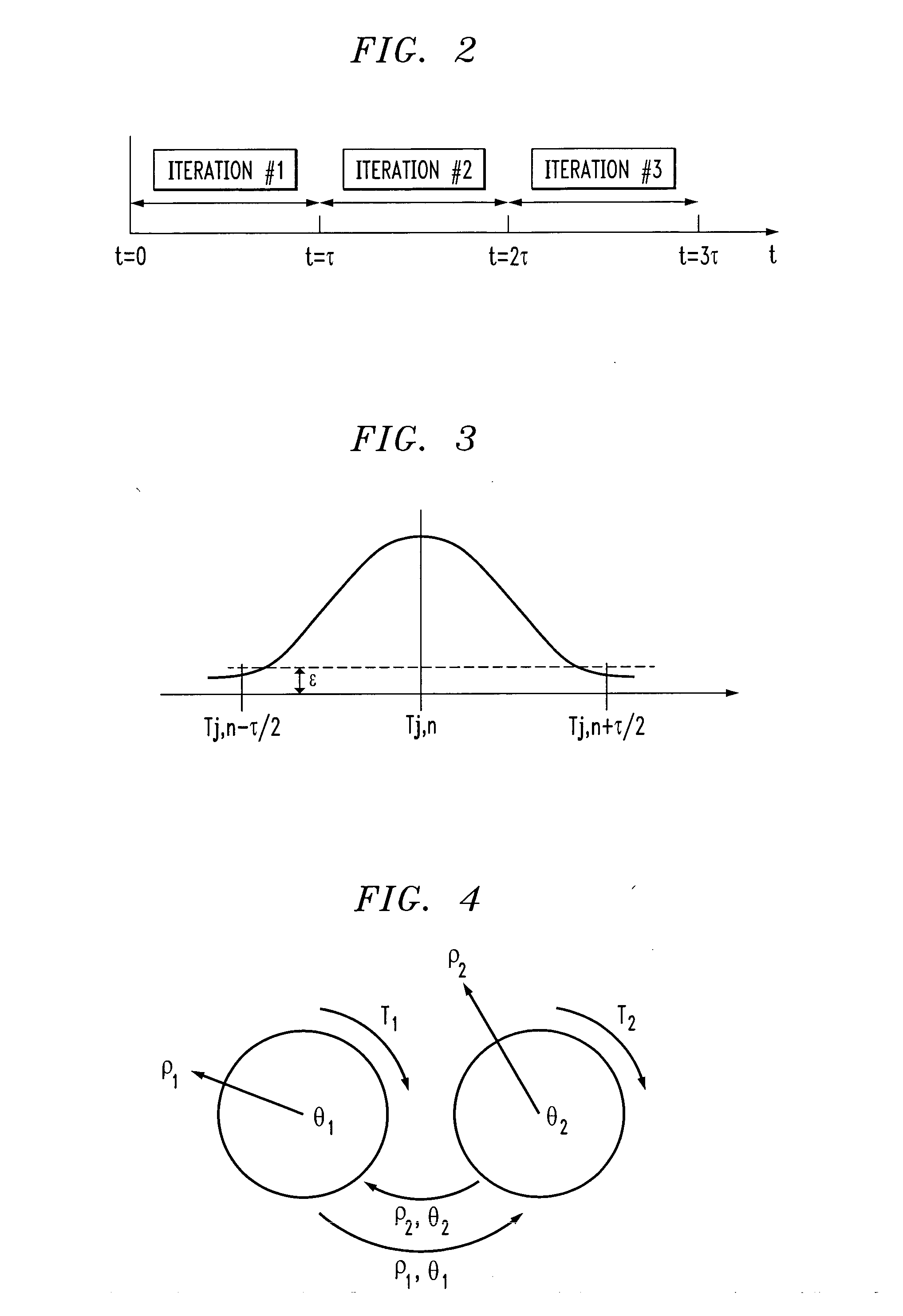
[0058] In the classifier element, timing information of signals processed by the element is modeled mathematically as follows. The output of a classifier element is denoted by Sj(t), where j is an index indicating the specific element. It is assumed that Sj (t) is constructed from two classes of waveforms. One is pulsatile and nearly periodic, and the other is nearly constant within the period of the pulsatile waveform. The underlying reason for modeling the signals in this way is that the model is intended to represent the aggregate behavior of a collection of neurons, and the effect this collection has on another collection of neurons. Though the preferred embodiment is described with reference to these two classes of waveforms, the analysis technique can be extended to multiple classes of waveforms in the spirit of this invention.

[0059] When Sj (t) is represented as a nearly constant value, the amplitude of the signal will be interpreted as the functional value of the classifier ...

second embodiment

[0071] In the classifier element, the amplitude and phase of an oscillator are used to implement the FM values. Thus, interactions between elements are not represented in terms of signal timing, but in terms of the phase of the signals, which in contrast with the previous embodiment are constantly compared and updated. Each FM element is an oscillator with the following variables: [0072] Phase: θ(t) ε [0,2π) [0073] Frequency: τ(t) [0074] Natural Frequency: τ0 ε [τmin, τmax][0075] Amplitude: ρ(t) ε [0,1]

The amplitude ρ can be considered to be the functional value of the classification. The phase θ of the classifier element is considered to be its membership value. The relationship between the phase of the input element and that of the receiving element plays a role in the computation of the output as follows.

[0076] Referring now to FIG. 4, a diagram illustrates a first classifier element interacting with a second classifier element. Classifier elements interact with each other by c...

third embodiment

[0085] In the classification element, a model that does not require the comparison of the incoming membership value with the receiving element's own membership value is used. The method operates as follows: [0086] An input layer consisting of receptors measures some property of the input. [0087] A layer (layer a) of integrate-and-fire model neurons receives inputs from the receptor layer, whose membrane potentials, in absence of other classes of inputs, are described by:

Via(t)=−gVia(t)+κIi(t)+εi(t) [0088] where g is a leakage term, Ii is the corresponding receptor input value, κ is a proportionality factor (usually the inverse of the capacitance), and εi is a stochastic process with zero temporal average. When the membrane potential reaches a specified threshold, the neuron fires a spike and its membrane potential is reset to its resting value, so that if Via(t)≧Vthsia(t)=1,Via(t)=VR otherwise sia(t)=1. [0089] A layer (layer b) of integrate-and-fire model neurons receives spiking in...


PUM


Abstract

The present invention provides techniques for transmitting at least one signal through an element of a classification system. One or more input signals are received at the element. One or more functional components are extracted from the one or more input signals, and one or more membership components are extracted from the one or more input signals. An output signal is generated from the element comprising a functional component and a membership component that correspond to one or more functional components and membership components from one or more input signals.

Description

FIELD OF THE INVENTION [0001] This present invention is related to techniques for transmitting and classifying signals in a classification system and, more particularly, for transmitting signals through a network of classifier elements with functional and membership components for classification purposes. BACKGROUND OF THE INVENTION [0002] In practice, a classifier receives a set of measurements or features as input, and assigns a category or class to this set. Thus, the classifier determines the mapping between an input set and a class. There are several types of classifiers, including those that learn, such as, for example, neural classifiers, and those that do not learn, such as, for example, rule-based expert systems. Classifier learning may be supervised or unsupervised. With regard to supervised learning, classes are pre-determined, and the classifier is trained on a set of input data with known classes. With regard to unsupervised learning, the classes are not pre-determined,...

Claims


Application Information

Patent Timeline
IPC IPC(8): G06F15/18G06N5/02
CPCG06K9/4628G06N99/005G06N20/00G06N5/02G06V10/454
Inventor CECCHI, GUILLERMO ALBERTOKOZLOSKI, JAMES ROBERTPECK, CHARLES CLYDE IIIRAO, RAVISHANKAR
Owner GOOGLE LLC
Learn More