Controlled centrifuge systems
a centrifuge and control technology, applied in the direction of centrifuges, rotary centrifuges, etc., can solve the problems of large physical size of the centrifuge, problems that can occur, and large energy required to process the mixtur
- Summary
- Abstract
- Description
- Claims
- Application Information
AI Technical Summary
Benefits of technology
Problems solved by technology
Method used
Image
Examples
Embodiment Construction
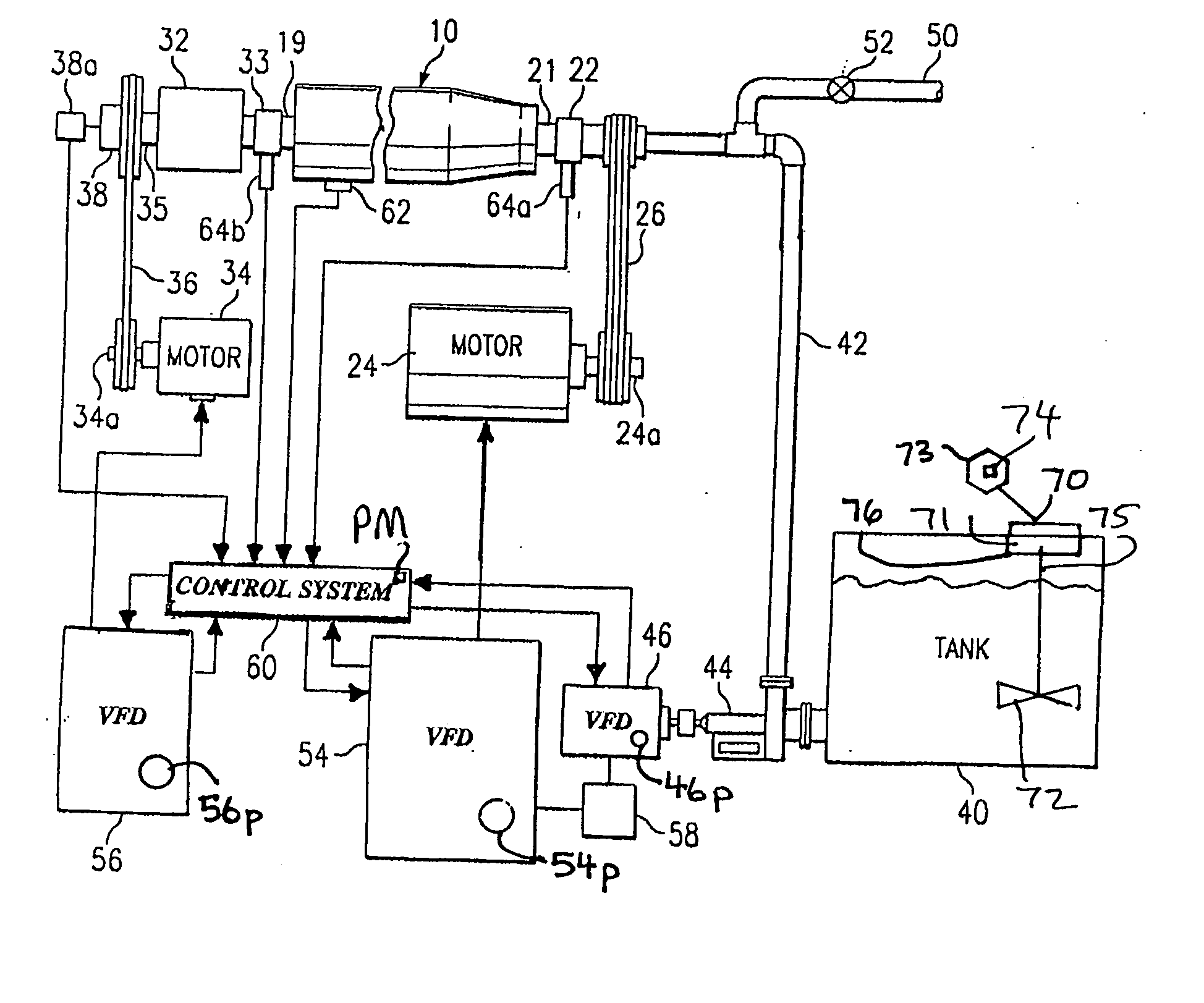
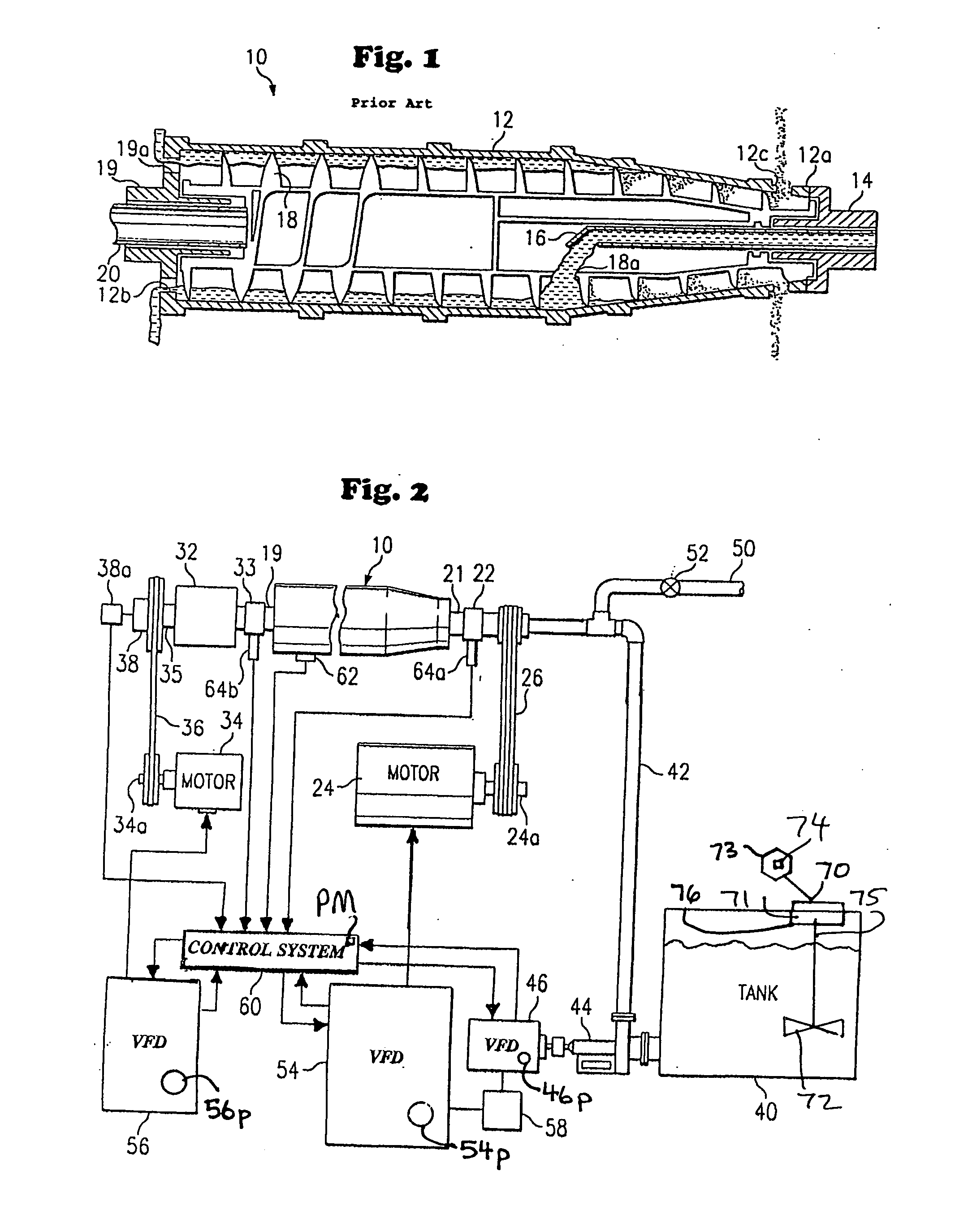
[0046] As shown in FIGS. 1 and 2, a centrifuge system 10 according to the present invention has a bowl 12, supported for rotation about its longitudinal axis, has two open ends 12a and 12b, with the open end 12a receiving a drive flange 14 which is connected to a drive shaft for rotating the bowl. The drive flange 14 has a longitudinal passage which receives a feed tube 16 for introducing a feed slurry, e.g. drilling material, into the interior of the bowl 12. A screw conveyor 18 extends within the bowl 12 in a coaxial relationship thereto and is supported for rotation within the bowl. A hollow flanged shaft 19 is disposed in the end 12b of the bowl and receives a drive shaft 20 of an external planetary gear box for rotating the screw conveyor 18 in the same direction as the bowl at a selected speed.
[0047] The wall of the conveyor 18 has one or more openings 18a near the outlet end of the tube 16 so that the centrifugal forces generated by the rotating bowl 12 move the slurry radia...
PUM
 Abstract
Description
Claims
Application Information
 - R&D
- Intellectual Property
- Life Sciences
- Materials
- Tech Scout
- Unparalleled Data Quality
- Higher Quality Content
- 60% Fewer Hallucinations
Browse by: Latest US Patents, China's latest patents, Technical Efficacy Thesaurus, Application Domain, Technology Topic, Popular Technical Reports.
© 2025 PatSnap. All rights reserved.Legal|Privacy policy|Modern Slavery Act Transparency Statement|Sitemap|About US| Contact US: help@patsnap.com


