
Connector housing, connector housing marking method, and method of inserting terminal metal fitting into connector housing

Active Publication Date: 2006-05-18
YAZAKI CORP
View PDF5 Cites 0 Cited by
  • Summary
  • Abstract
  • Description
  • Claims
  • Application Information

AI Technical Summary

Benefits of technology

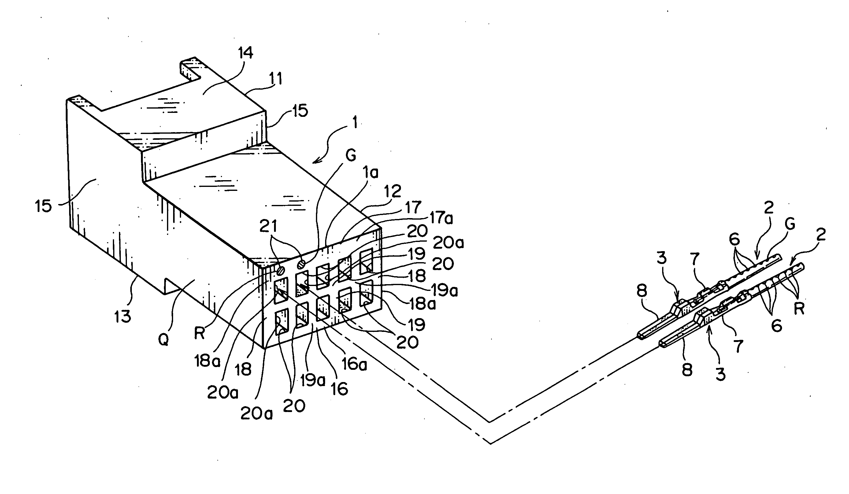
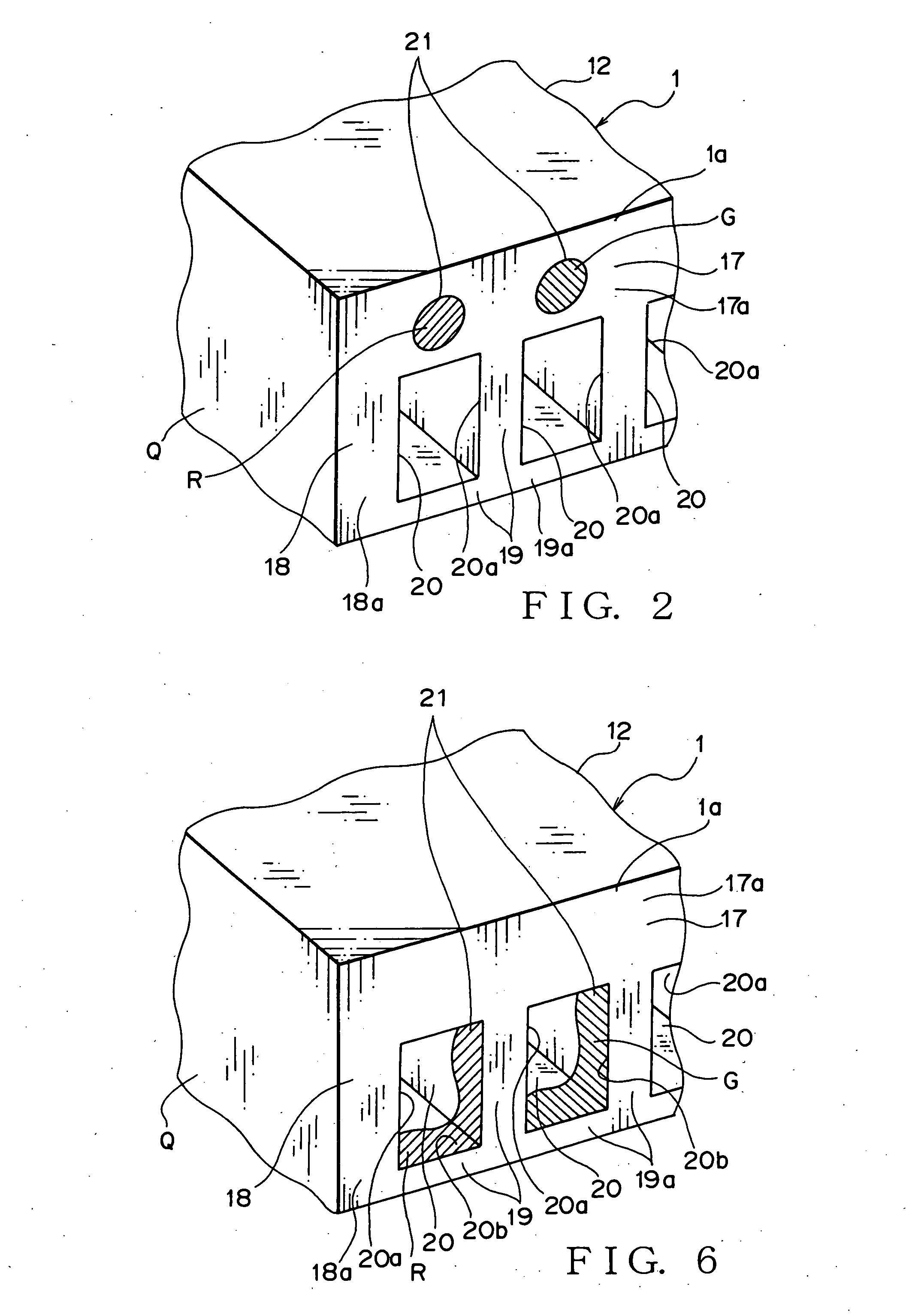
[0023] According to the present invention as defined in claim 2, the mark is provided on the surface of one of the partition walls surrounding the opening of the terminal-receiving chamber. Therefore, the mark can be easily recognized and the displacement between the mark and the connector housing can be prevented.
[0033] According to the present invention as defined in claim 9, the mark is provided at an end near the opening of the inner surface of the terminal-receiving chamber. Therefore, the mark can be easily recognized and the displacement between the mark and the connector housing can be prevented. Further, since the mark is provided on the inner surface of the terminal-receiving chamber, a correspondence error between the mark and the terminal-receiving chamber can be prevented. Accordingly, since the mark can be easily recognized and the correspondence error between the mark and the terminal-receiving chamber can be prevented, by inserting by turns the metal-terminal indicated by the mark into the mating terminal-receiving chamber corresponding to the mark, the metal terminal can be prevented from being inserted into a wrong terminal-receiving chamber.

Problems solved by technology

When extracting the metal terminal from the wrong terminal-receiving chamber 101, the metal terminal may be damaged.

Method used


Image

  • Connector housing, connector housing marking method, and method of inserting terminal metal fitting into connector housing
  • Connector housing, connector housing marking method, and method of inserting terminal metal fitting into connector housing
  • Connector housing, connector housing marking method, and method of inserting terminal metal fitting into connector housing

Examples


Embodiment Construction

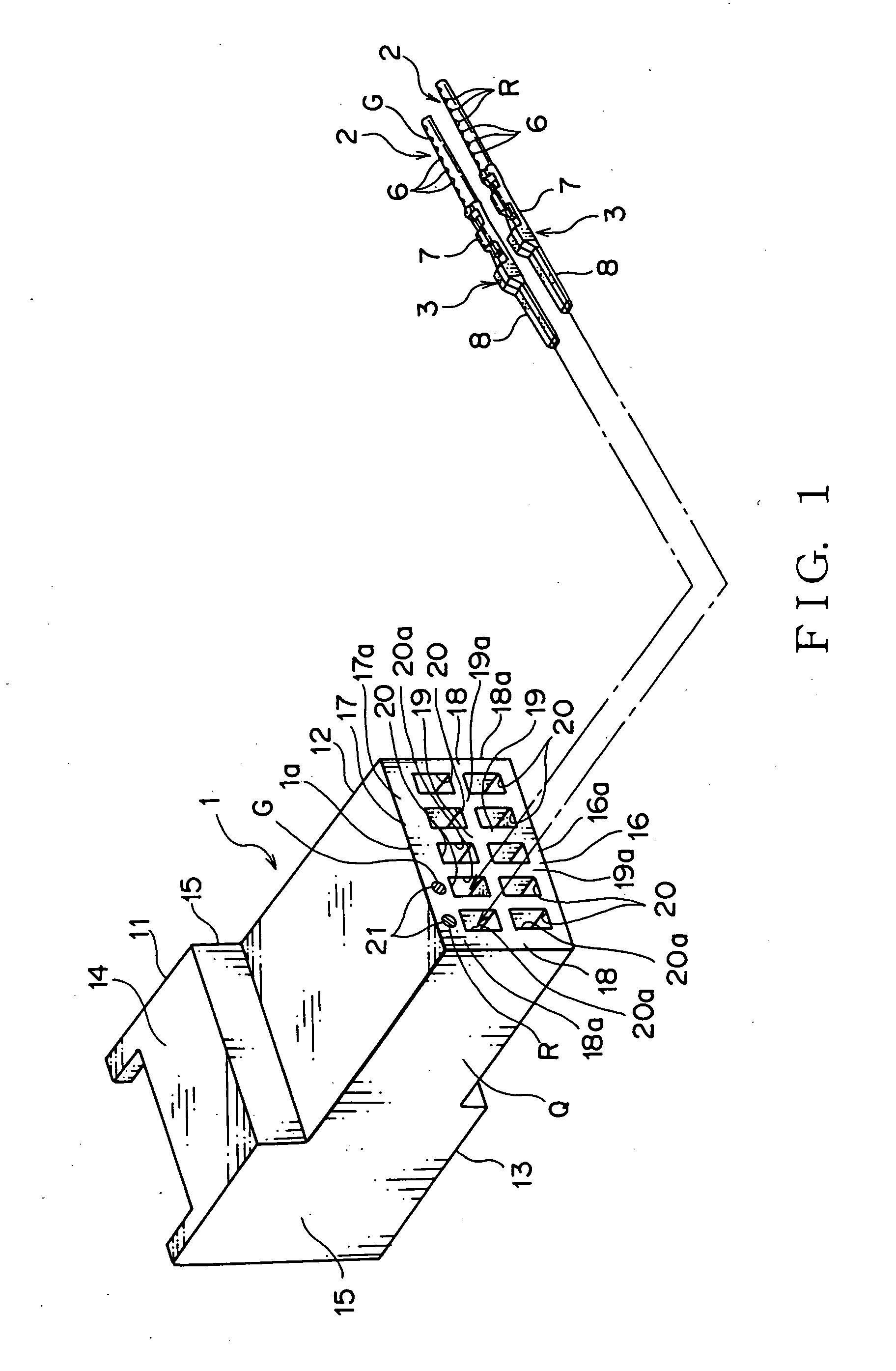
[0041] A connector housing as an embodiment of the present invention will now be described with reference to FIG. 1 to 5. A connector housing 1 as shown in FIG. 1 receives a male metal terminal 3 (hereinafter called “male terminal”), to which electric wire 2 is attached, to compose a wire harness for wiring in such as a vehicle. In addition, only two of the male terminals 3 are shown, and the rest of the male terminals 3 are omitted in FIG. 1.

[0042] As shown in FIG. 3 and 4, the electric wire 2 comprises a conductive core wire 4 and an insulating sheath part 5. The core wire 4 is made by twisting a plurality of strands. The strand composing the core wire 4 is made of conductive metal. Additionally, the core wire 4 may be composed of one strand. The sheath part 5 is made of synthetic resin such as Polyvinylchloride (PVC). Since the sheath part 5 covers the core wire 4, an outer surface 5a of the sheath part 5 composes an outer surface of the electric wire 2.

[0043] In addition, a co...


PUM


Abstract

An object of this invention is to provide a connector housing which can be prevented a terminal-receiving chamber from receiving a wrong metal terminal. A connector housing 1 comprises a plurality of terminal-receiving chambers 20 and a plurality of marks 21. The terminal-receiving chamber 20 receives a male terminal 3. Electric wire 2 is attached to the male terminal 3. A mark 6 is formed on an outer surface 5a of the electric wire 2. A color of the mark 6 of one electric wire 2 is a first color R. A color of the mark 6 of the other electric wire 2 is a second color G. The first color R is different from the second color G. The mark 21 corresponds to each terminal-receiving chamber 20. A color of one mark 21 is the first color R, which is the same as the color of the mark 6 of the one electric wire 2. A color of the other mark 21 is the second color G, which is the same as the color of the mark 6 of the other electric wire 2. By forming the mark 21 in a same color as the mark 6 of the electric wire 2 attached to the male terminal 3 which is to be inserted into the terminal-receiving chamber 20 corresponding to the mark 21, the mark 21 indicates the male terminal 3 to be received by the terminal-receiving chamber 20 corresponding to the mark 21.

Description

TECHNICAL FIELD [0001] This invention relates to an electric connector housing, a method for marking the electric connector housing and a method for inserting a metal terminal into the electric connector housing. BACKGROUND ART [0002] A various electrical components are mounted on a mobile body such as a vehicle. Accordingly, a wire harness is arranged to communicate electric power from a battery, a control signal from a computer, and the like to the electrical components in the vehicle. The wire harness includes a plurality of electric wire and an electric connector attached to ends of the electric wire. [0003] The electric wire includes conductive core wire and a sheath made of insulating synthetic resin for coating the core wire. The electric wire is what is called coated electric wire. The electric wire is made by extruding insulating synthetic resin around the core wire. When carrying out the extrusion coating, coloring agent for a desired color is mixed with the synthetic resi...

Claims


Application Information

Patent Timeline
IPC IPC(8): H01R3/00H01R13/46H01R13/642H01R43/20
CPCH01R13/465H01R13/642H01R43/20
Inventor KAMATA, TAKESHIYAGI, KIYOSHISUZUKI, SHIGEHARUSUGIMURA, KEIGO
Owner YAZAKI CORP
Learn More