
Spinal rod cross connector

Active Publication Date: 2006-03-23
ZIMMER BIOMET SPINE INC
View PDF99 Cites 88 Cited by
  • Summary
  • Abstract
  • Description
  • Claims
  • Application Information

AI Technical Summary

Benefits of technology

[0008] The foregoing and other features, utilities and advantages of the invention will be apparent from the followin

Problems solved by technology

One difficulty with connecting the elongated rods using cross-connecting devices resides in the fact that the pair of elongated rods is not exactly parallel and equally spaced along the spine.
While providing separate devices provides a satisfactory solution relating to the coupling the cross connecting devices to the pair of elongated rods, it causes different problems.
One such problem, for example, is that the force required to satisfactorily connect to separate devices provides stresses to the cross connecting devices that may cause twisting and bending of the pair of elongated rods.

Method used


Image

  • Spinal rod cross connector
  • Spinal rod cross connector
  • Spinal rod cross connector

Examples


Embodiment Construction

[0021] The present invention relates to a device that traverses a spinal column to connect a pair of elongated rods being used to correct spinal abnormalities, such as, for example, spinal curvature.

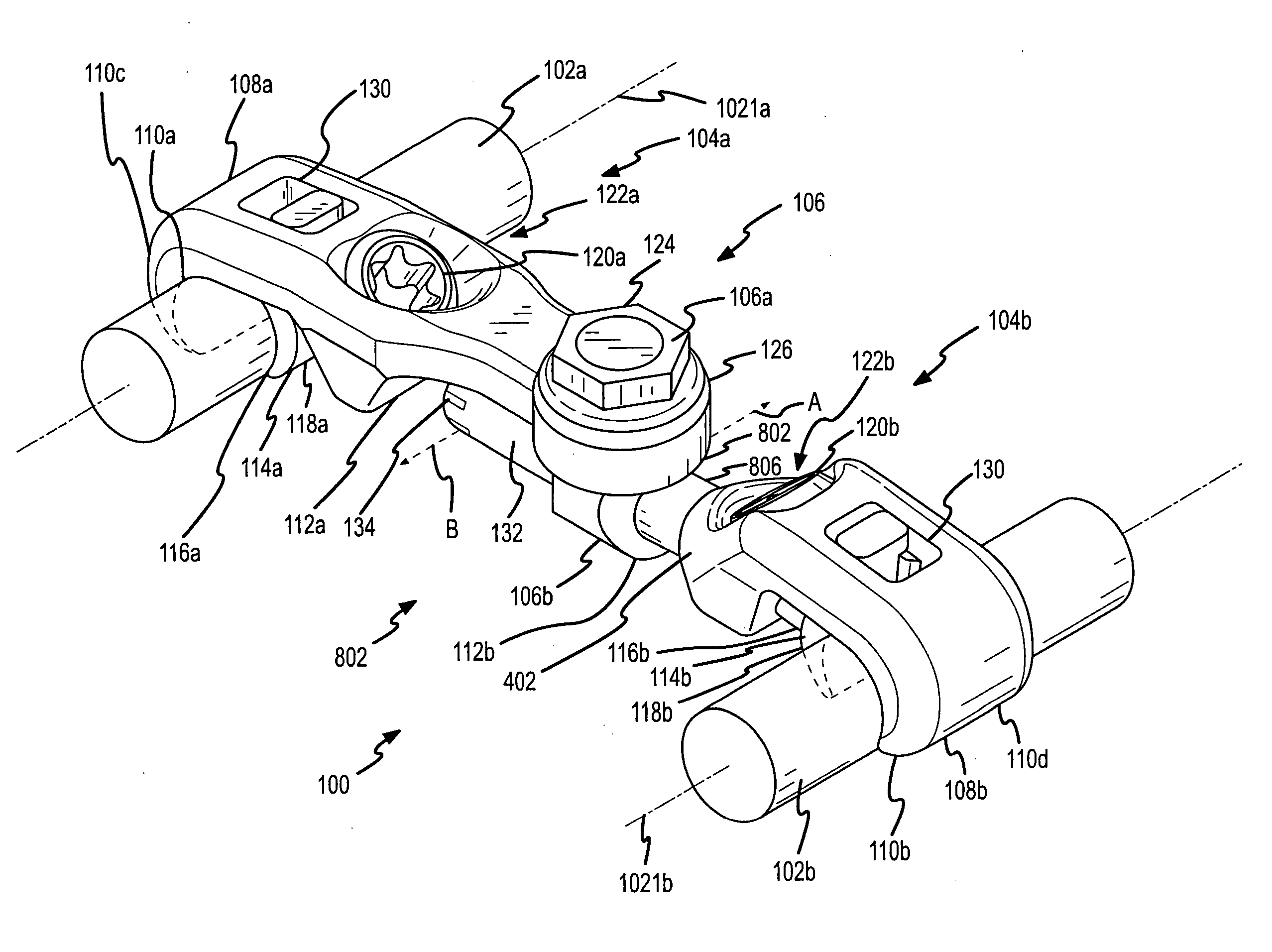
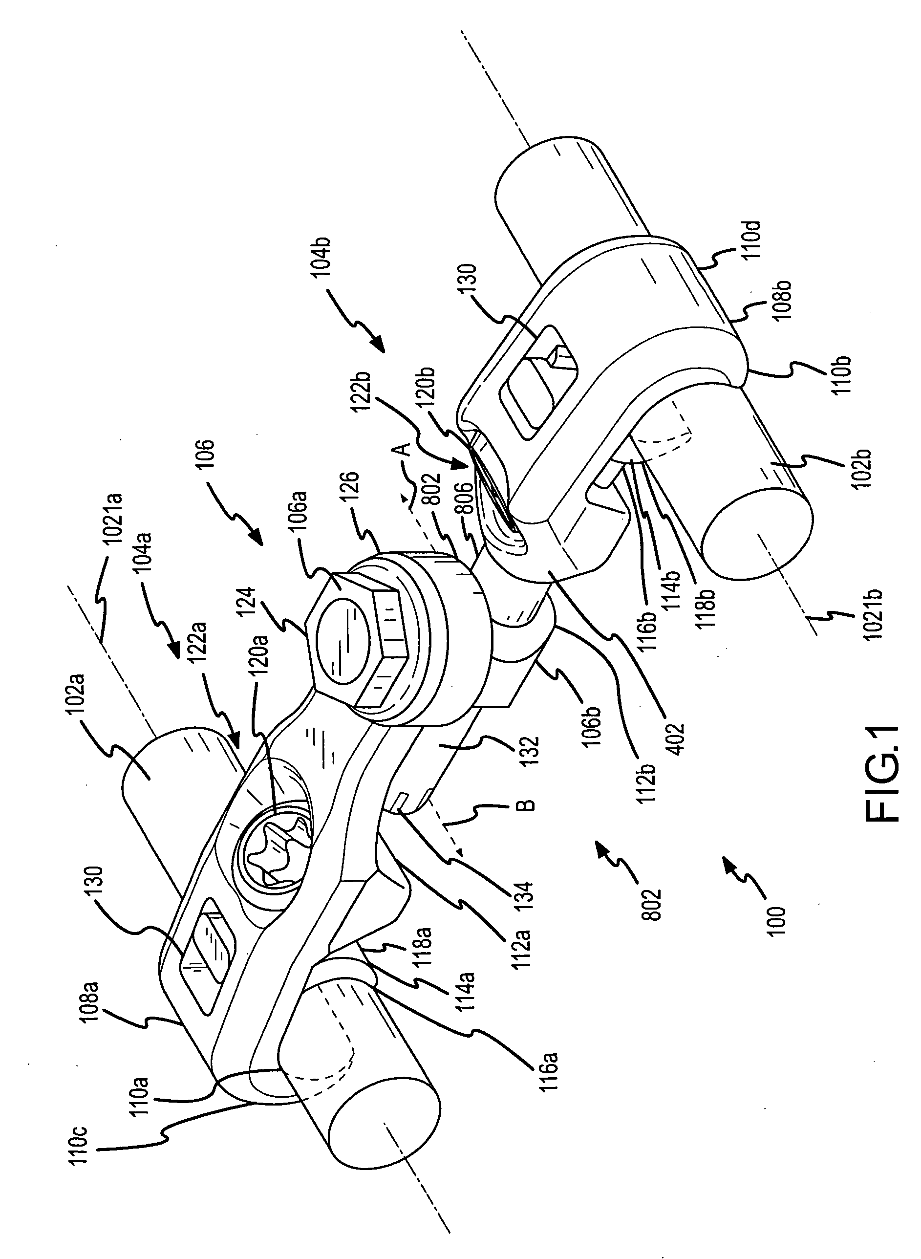
[0022] Referring now to FIG. 1, a top perspective view of a cross connector 100 is shown. Cross connector 100 is shown attached to a pair of elongated spinal fixation rods 102a and 102b. Spinal fixation rods 102a and 102b would be connected to the pedicle portion of vertebral bodies about the spinal column as is generally known in the art (not shown). Related application Ser. No. 10 / 915,902 mentioned above describes a novel device for attaching spinal fixation rods 102a and 102b to the pedicles.

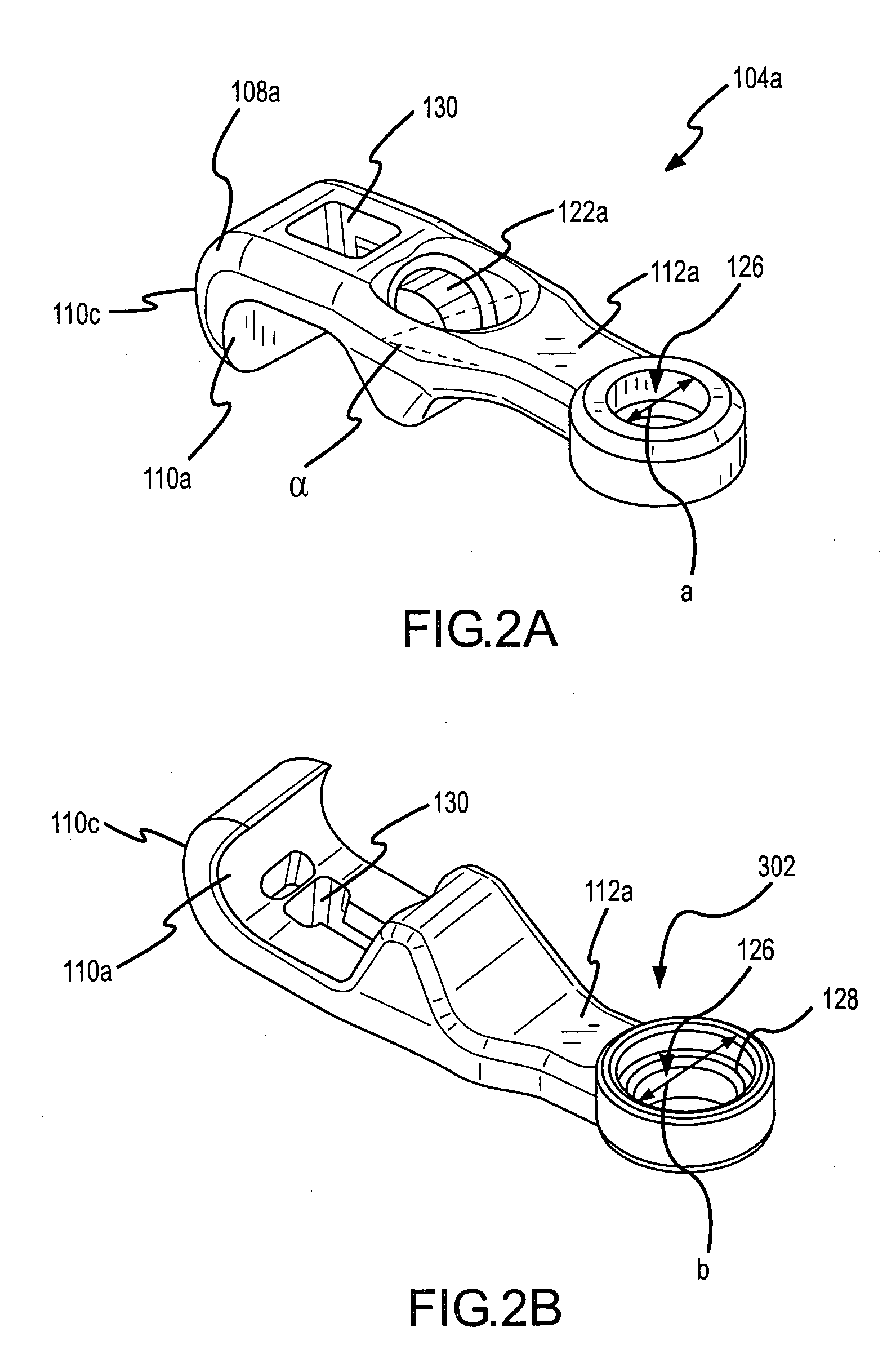
[0023] Cross connector 100 comprises at least two independently movable parts coupled together. A first part 104a, sometimes referred to as bar arm 104a, connected to spinal fixation rod 102a and a second part 104b, sometimes referred to as rod arm 104b, connected to spinal fixation rod 104b. Ba...


PUM


Abstract

The cross connecting device includes a bar arm coupled to one of a pair of posterior rods or spinal fixation rods and a rod arm coupled to the other of the pair of the rods. The bar arm and rod arm are coupled together by a connector or coupling device. The coupling device has a shank extending through a bore in the bar arm and a connector bore through which a protrusion on the bar arm extends. The bar arm is rotationally movable in the connector bore. The shank is rotationally and translationally movable in the bar arm bore. The coupling device is vertically movable through the bore. The protrusion is rotationally and translationally movable in the connector bore. The cross connecting devices are coupled to the rods by a pair of opposing surface to surface contacts formed by a surface of a hook end and a surface of a pad.

Description

RELATED APPLICATION [0001] This application claims priority to U.S. Provisional Patent Application Ser. No. 60 / 607,231, titled SPINAL ROD CROSS CONNECTOR, filed Sep. 3, 2004, incorporated herein by reference as if set out in full. This application is related to co-pending U.S. patent application Ser. No. 10 / 915,902, titled SCREW AND ROD FIXATION SYSTEM, filed Aug. 10, 2004, and incorporated herein by reference as if set out in full.FIELD OF THE INVENTION [0002] The present invention relates to devices useful in correcting spinal abnormalities and, more particularly, the invention is related to a cross connector that enhances the rigidity and stability of the devices useful in correcting spinal abnormalities. BACKGROUND OF THE INVENTION [0003] As is generally known in the art, spinal abnormalities may be correctable using a pair of posterior spinal fixation rods attached to the vertebrae using pedicle screws and the like. One such spinal fixation system is described in co-pending, re...

Claims


Application Information

Patent Timeline
IPC IPC(8): A61F2/30
CPCY10T74/22A61B17/7052
Inventor THRAMANN, JEFFERYFULTON, MICHAEL
Owner ZIMMER BIOMET SPINE INC
Learn More