
Ink reservoir for automatic recording, writing, and drawing devices

a technology of automatic recording and drawing, applied in the field of inkjet systems, can solve the problems of drop, ink supply to the printing head, and the inability to remove the reservoir or the only removable one,

Inactive Publication Date: 2006-03-16
J S STAEDTLER
View PDF16 Cites 15 Cited by
  • Summary
  • Abstract
  • Description
  • Claims
  • Application Information

AI Technical Summary

Benefits of technology

[0008] It is the object of the present invention to provide an ink reservoir which does not have the disadvantages discussed above and which permits an easy removal of the used, partially empty or empty reservoir from the printer.

Problems solved by technology

This tank or reservoir has the disadvantage that the pressure system composed of pressing device and ink reservoir rests against the housing, so that the housing expands in the shape of a drum which has the result that the reservoirs are no longer removable or are only removable by applying high forces from the ink compartment of the printer.
This has the disadvantage that the reservoirs to which pressure is admitted bulge or become untight which has the result that a pressure drop occurs and the ink supplied to the printing head is interrupted.
The reservoirs are also structurally very complicated and require a plurality of reinforcing ribs in order to counteract any deformation.
The problem of bulging or expanding reservoirs occurs generally in all known types of pressure tank systems.

Method used


Image

  • Ink reservoir for automatic recording, writing, and drawing devices
  • Ink reservoir for automatic recording, writing, and drawing devices
  • Ink reservoir for automatic recording, writing, and drawing devices

Examples


Embodiment Construction

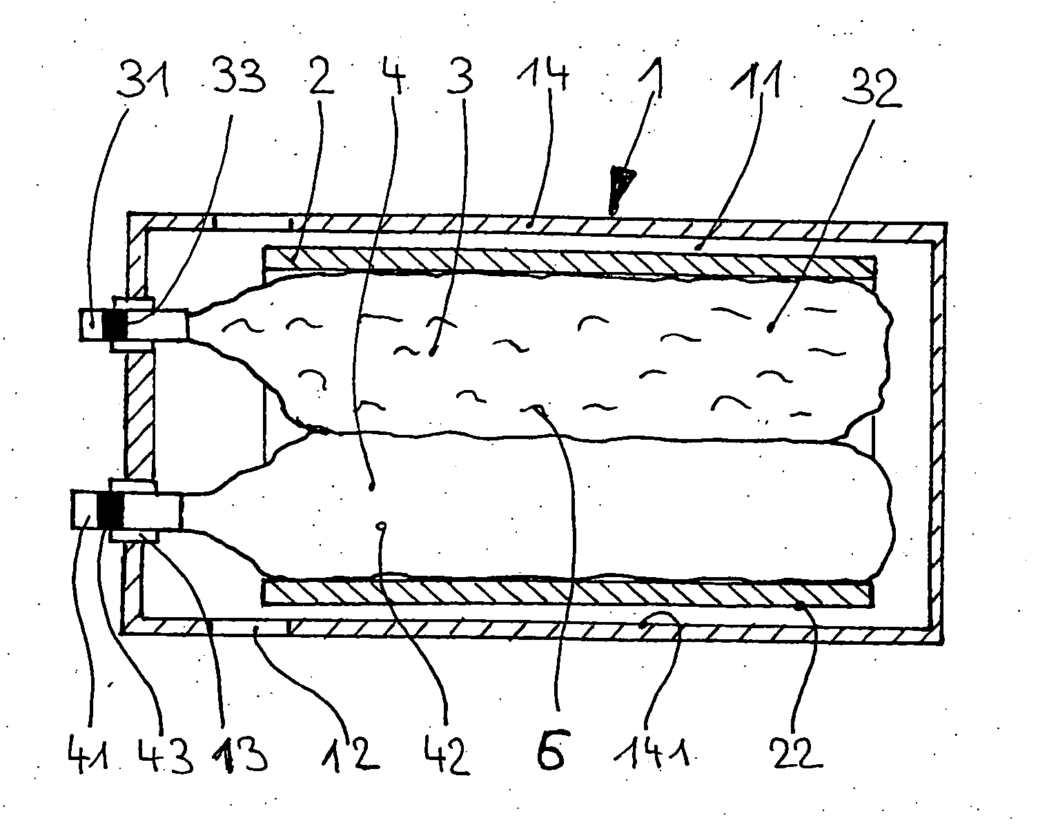
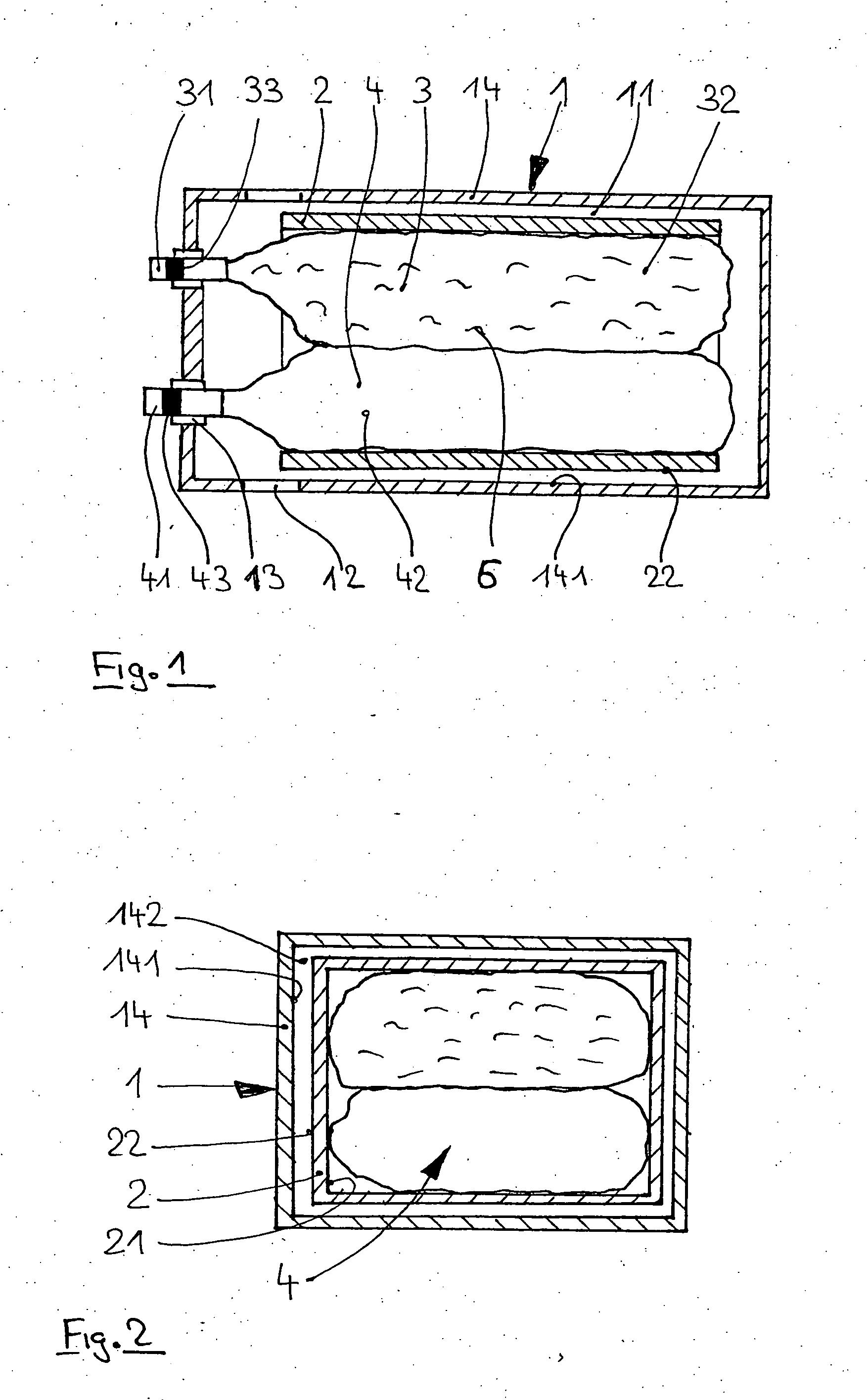
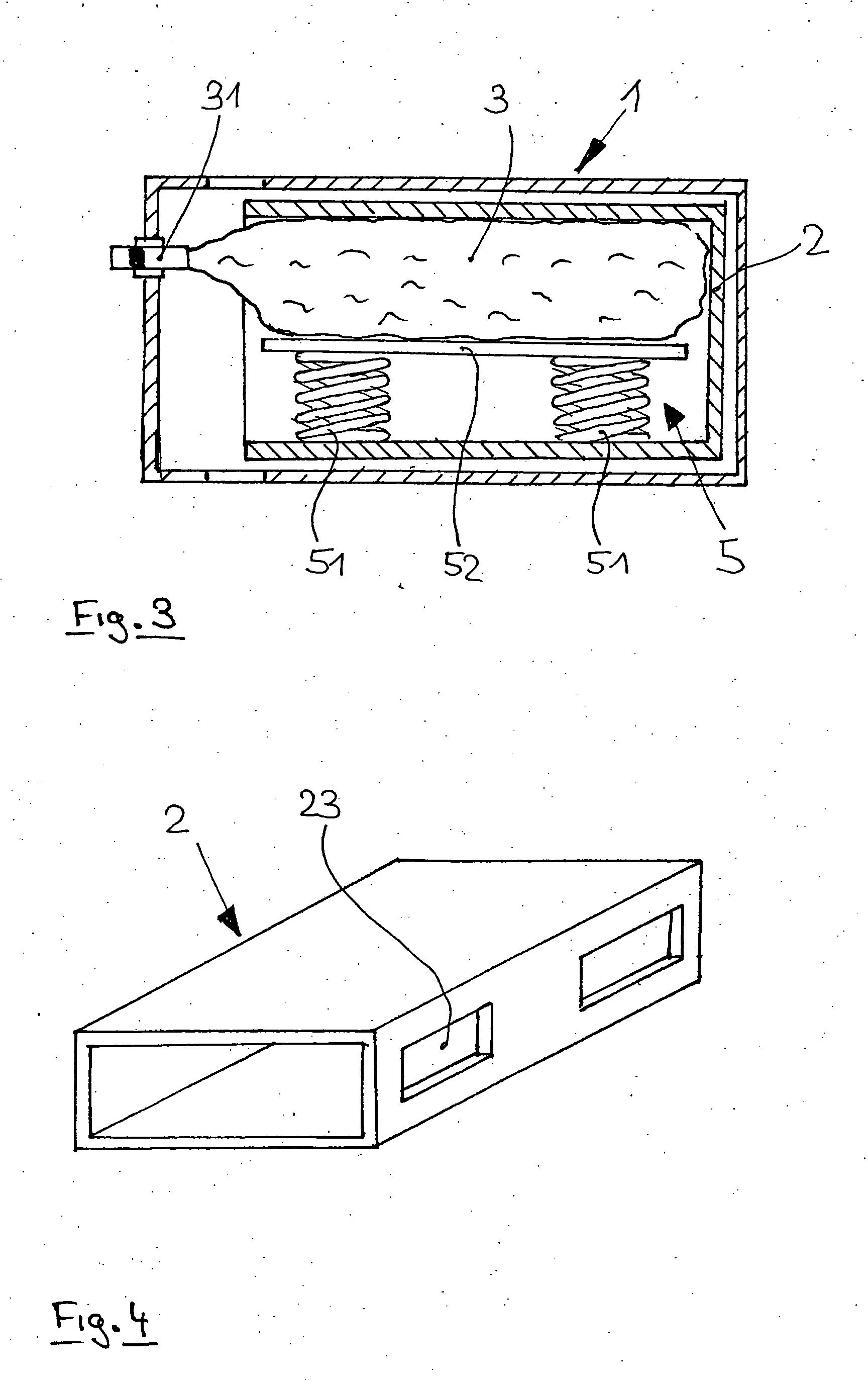
[0016]FIG. 1 of the drawing shows the principal configuration of an ink reservoir 1 proposed in accordance with the present invention, wherein the inner space 11 of the reservoir is defined by the housing wall 14. Arranged in the interior 11 of the reservoir are the ink pouch 3 for storing ink 6 in the interior 32 of the pouch and the air bag 4, wherein the ink reservoir 3 and the air bag 4 are surrounded by a bandage 2. The illustrated ink reservoir 3 as well as the air bag 4 are constructed of a flexible material. The interior 42 of the air bag 4 is subjected to a pressure medium, preferably compressed air, so that the interior 42 expands and presses the ink 6 contained in the interior space 32 of the pouch from the ink pouch 3. The bandage or sleeve 2 always ensures that no forces act on the inner side 141 of the housing through the air bag 4 through which compressed air is admitted.

[0017] No forces act between the outer wall 22 of the bandage 2 and the inner side 141. Any force...


PUM


Abstract

An ink reservoir or tank for automatic recording, writing, and drawing devices, particularly ink-jet systems, such as printers and plotters, wherein a sleeve or bandage is arranged within the ink reservoir. The ink pouch and the printing device are entirely or partially surrounded by the sleeve or bandage. In addition, the sleeve or bandage is constructed with respect to shape and dimensions in such a way that a free space exists between the outer wall of the sleeve or bandage and the inner side of the housing wall of the ink reservoir.

Description

BACKGROUND OF THE INVENTION [0001] 1. Field of the Invention [0002] The present invention relates to an ink reservoir or tank for automatic recording, writing, and drawing devices, particularly ink-jet systems, such as printers and plotters. [0003] 2. Description of the Related Art [0004] Ink reservoirs for devices of the above-described type are known in principle. [0005] DE 102 27 225 A1 shows and describes an ink reservoir with a stiff housing with a compressable ink pouch in the housing, wherein a pressing device for compressing the flexible ink reservoir is coupled to the ink pouch. This tank or reservoir has the disadvantage that the pressure system composed of pressing device and ink reservoir rests against the housing, so that the housing expands in the shape of a drum which has the result that the reservoirs are no longer removable or are only removable by applying high forces from the ink compartment of the printer. [0006] In addition, US 2001 / 0024225 A1 discloses an ink r...

Claims


Application Information

Patent Timeline
Patent Type & Authority Applications(United States)
IPC IPC(8): B41J2/175
CPCB41J2/17513B41J2002/17516B41J2/17556B41J2/17523B41J23/02
Inventor SCHUSTER, RAINERENGEL, STEFAN
Owner J S STAEDTLER
Learn More