
Muscle-powered continuously variable drive system and apparatus having same

a drive system and muscle technology, applied in the direction of rider propulsion, vehicle components, transportation and packaging, etc., can solve the problems of excessive mechanical complexity of muscle-power drive systems, weight and mechanical efficiency penalties, etc., and achieve the effect of better use of leg muscle power

Inactive Publication Date: 2006-03-16
LINEARC
View PDF11 Cites 11 Cited by
  • Summary
  • Abstract
  • Description
  • Claims
  • Application Information

AI Technical Summary

Benefits of technology

[0006] The invention is directed to a light-weight, mechanically simple, ergonomically efficient muscle-power drive system suitable for use in limb-driven human-powered apparatus and machinery such as bicycles, tricycles, wheel chairs, etc. The ergonomic improvement is achieved in the present invention through a reciprocating-motion design. When used in a bicycle, the drive system of the present invention is believed to make better use of leg muscle power as compared to conventional rotary cranking motion drive systems such as used in a conventional bicycle.
[0007] The invention enables the complete elimination of the conventional rotary-pedal bicycle's front, or crank, hub and bearings, with attendant simplification of the frame design and substantial weight savings. The invention also allows for partial-stroke propulsion (i.e., continuous application of power using less-than-full-length strokes), and mass centralization due to the continuously-side-by-side positioning of the rider's legs. Both of these features are particularly advantageous in off-road riding.
[0011] The respective positions of the coupling points is adjustable and can range from close to the pivot end of the actuator lever, to close to the pedal surfaces at the end opposite the pivot end. The geometry of the tether and the idler pulleys thereby provides continuously variable lever-travel-to-wheel-travel ratios over a useful range. This eliminates the need for multiple sprockets and derailleur mechanisms, or internal gear hubs, as used on conventional rotary-pedal bicycles.

Problems solved by technology

Unfortunately, the prior art muscle-power drive systems suffer from excess mechanical complexity, incurring both weight and mechanical efficiency penalties.

Method used


Image

  • Muscle-powered continuously variable drive system and apparatus having same
  • Muscle-powered continuously variable drive system and apparatus having same
  • Muscle-powered continuously variable drive system and apparatus having same

Examples


Embodiment Construction

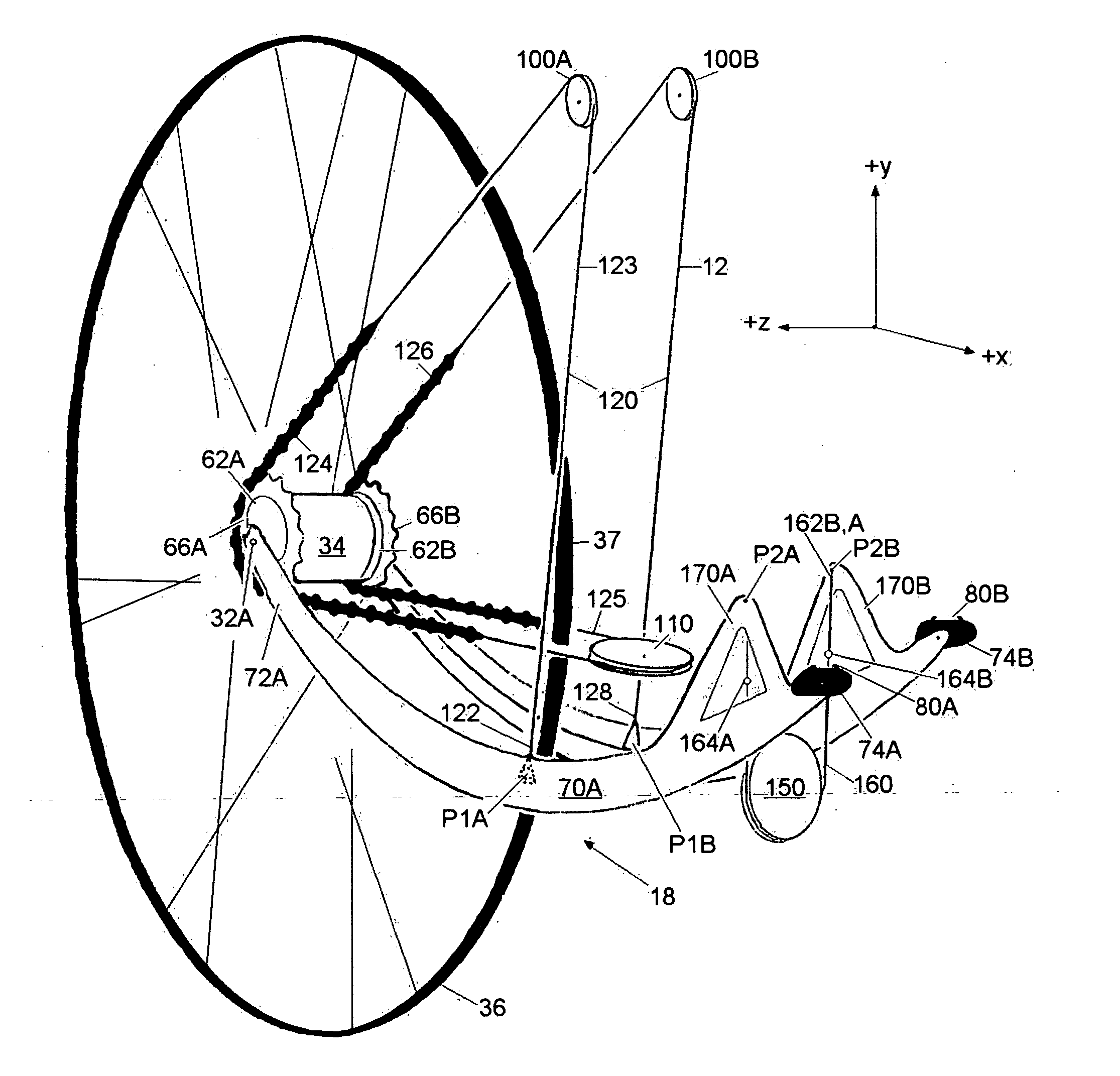
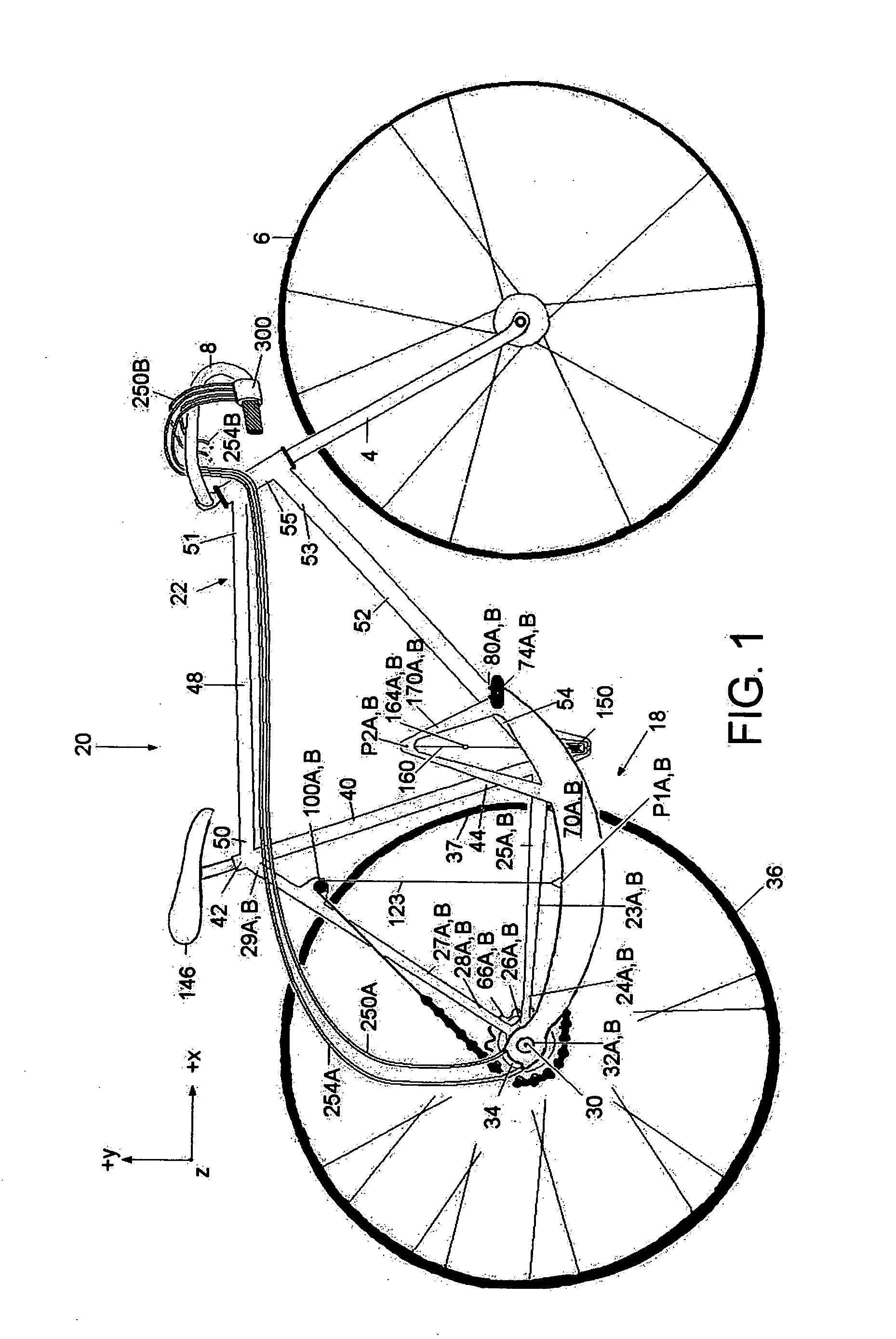
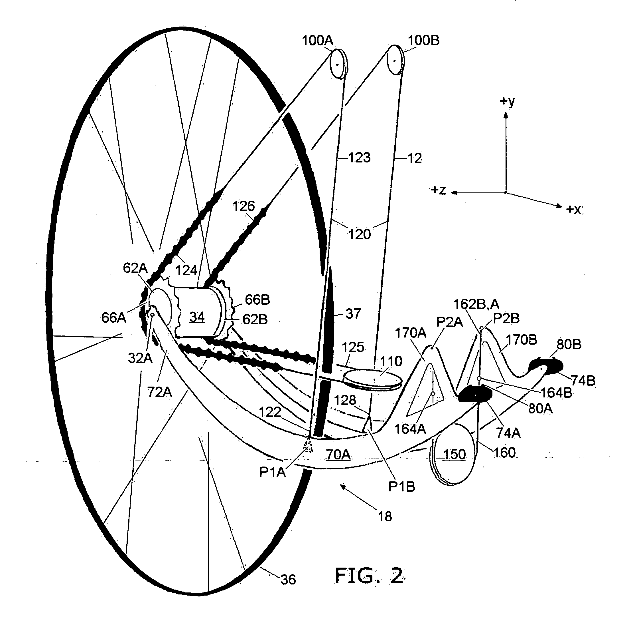
[0021]FIG. 1 is a side elevational view of an example embodiment of a muscle-powered drive system (“the drive system”) 18 of the present invention as incorporated into a bicycle 20. An X-Y-Z Cartesian coordinate system is shown in for the sake of reference, wherein “vertical” is in the Y-direction, and horizontal is in the Z- and X-directions. Also, “front” is associated with the +X direction, the “back” is associated with the −X direction, the “top” or “up” is associated with the +Y direction, the “bottom” or “down” is associated with the −Y direction, the right-hand side is associated with the +Z direction, and the left-hand side is associated with the −Z direction. Also, “horizontal” means in or substantially in the X-Z plane, while “vertical” means in or substantially in the Y-Z plane. Thus, “vertical” and “horizontal” are intended to generally indicate relative orientations.

The Frame

[0022] Bicycle 20 has a frame 22 that is aligned substantially in the X-Y plane. Bicycle fram...


PUM


Abstract

A muscle-powered continuously variable drive system, and apparatus having same, is disclosed. The system employs dual actuator levers pivoted at one end. The free pedal ends of the levers reciprocate through an arcuate range of motion via application of muscle power by the user, rather than cycling through complete revolutions of a small-radius circle, such as is common for conventional bicycles. The reciprocating motion of the levers initiated by the user generates a force that is translated into rotational motion of a drive wheel via a drive tether. The drive tether is attached to the actuator levers and runs around three idler pulleys mounted to the apparatus' frame. Two chain segments of the tether engage respective dual sprockets at the hub of the drive wheel. The geometry of the transmission enables a light, simple, system of continuously-variable torque multiplication, which eliminates the need for conventional derailleurs and multiple sprockets, or internal gear hubs.

Description

CLAIM OF PRIORITY [0001] This application claims priority under 35 USC § 119(e) from U.S. Provisional Patent Application No. 60 / 651,483, filed on Sep. 13, 2004.FIELD OF THE INVENTION [0002] The invention relates to muscle-powered drive systems and apparatus having same. BACKGROUND ART [0003] There are a number of transportation devices such as bicycles that rely on muscle-power drive systems. Conventional bicycles, for example, have a front chain wheel (“chain ring”) to which pedals are attached. The pedals are arranged to allow a user to drive the front chain wheel by pedaling in cyclical fashion with their feet while sitting atop the bicycle. The front chain ring is mechanically coupled to a rear freewheel by a chain. The rear freewheel is operably arranged at the hub of the rear wheel of the bicycle, and typically has multiple sprockets so that the user can select between different gears. In operation, the user causes his or her legs to exert a downward force on the pedals to ini...

Claims


Application Information

Patent Timeline
IPC IPC(8): B62M1/08
CPCB62M1/28
Inventor NORMAN, STEPHEN
Owner LINEARC
Learn More