
Device for protection against voltage surges with mobile electrode

Active Publication Date: 2006-03-02
SCHNEIDER ELECTRIC IND SAS
View PDF5 Cites 4 Cited by
  • Summary
  • Abstract
  • Description
  • Claims
  • Application Information

AI Technical Summary

Benefits of technology

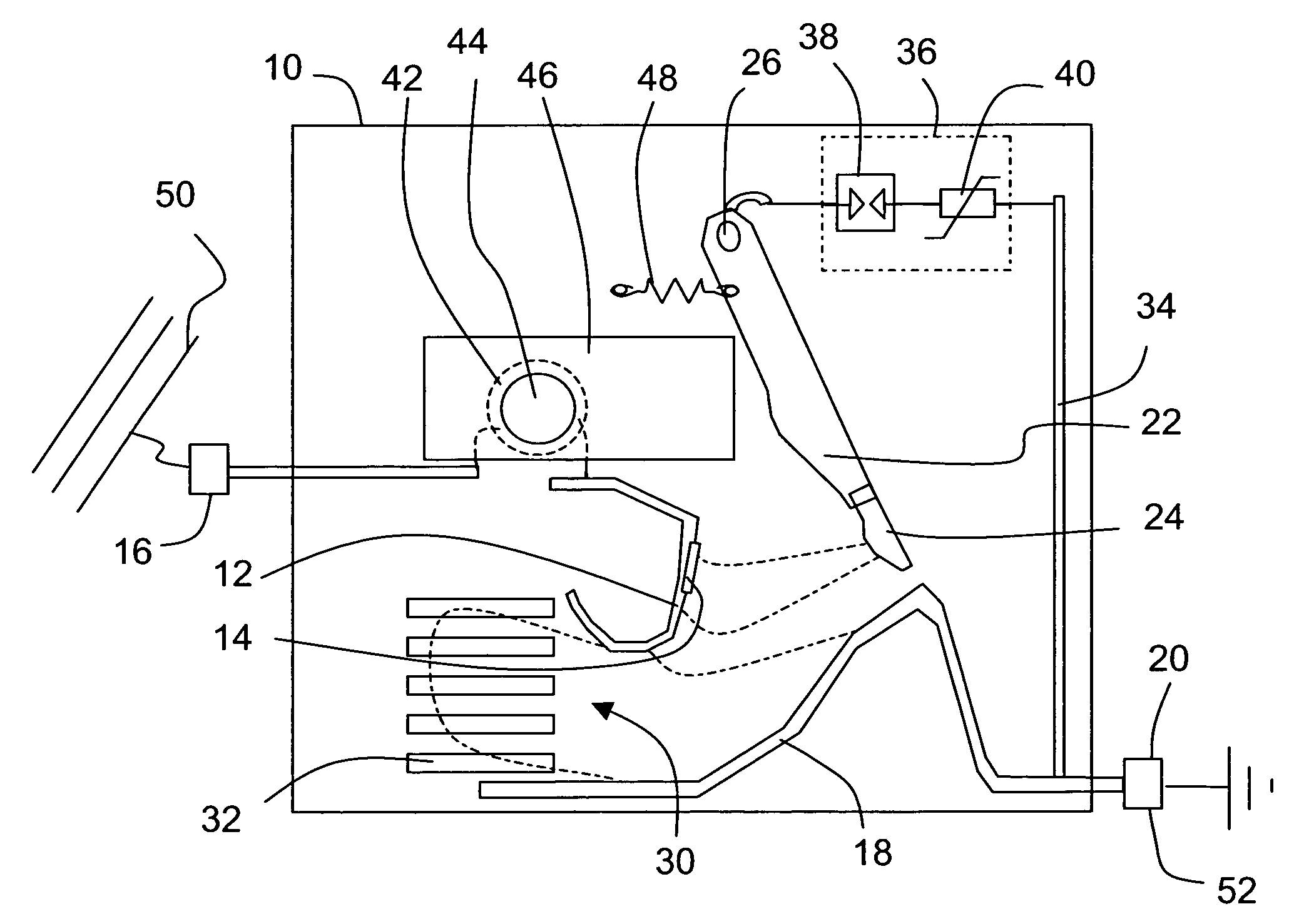
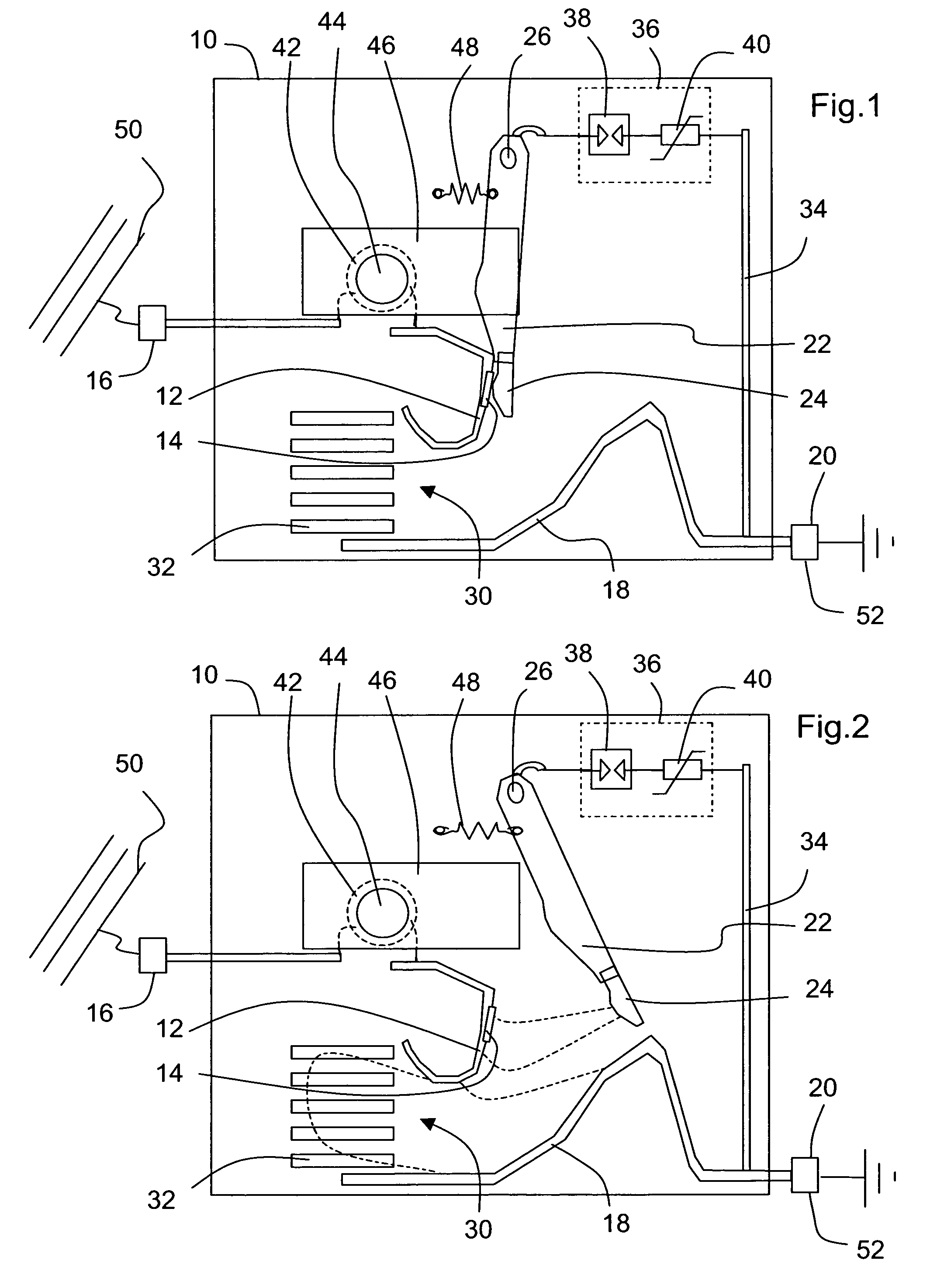
[0014] By moving the switching electrode to the switching position, an electric arc is first created between the mobile electrode and the first connecting electrode, which has the immediate effect of limiting the current flowing in the dipole. When the switching electrode approaches the switching position, the electric arc switches between the connecting electrodes, thus switching the electric dipole out of the circuit. Double protection of the dipole is thus achieved.
[0015] Preferably, the electric dipole is connected in series between the switching electrode and the second connecting pad. The device obtained is then particularly simple. It is in particular possible to provide for the mobile electrode in the operating position to be in contact with the first connecting electrode.

Problems solved by technology

When a large voltage surge characteristic of a lightning flash in immediate proximity to the device occurs between the terminals, the variable resistor reacts first but the voltage at the terminals of the spark arrester is sufficient for the spark arrester to be turned on, which enables the current subsequently flowing in the variable resistor to be limited.
However, the branch of the circuit comprising the variable resistor remains turned on when the spark arrester comes into operation.
The variable resistor is therefore not efficiently protected in case of a long follow current wave.
There is therefore a risk of the variable resistor being damaged.
When the variable resistor is damaged, it lets a leakage current flow in continuous manner.
In addition, it is liable to no longer reach the ignition voltage of the spark arrester.
This imposes the use of components with low current / voltage characteristic dispersion, the characteristics whereof are relatively constant in time, resulting in a high cost price.
However, this artifice does not overcome the problem of premature ageing of the variable resistor.
In addition, it appears difficult to define with precision the ignition voltage of the device, which will be tributary to the state of the surface of the resistive electrode and of the metallic electrode facing the latter, to the characteristics of the resistive electrode and to all the parameters characteristic of the breakdown voltage in the gas in which the electrodes are immersed, i.e. as a first approximation the distance between the resistive electrode and the electrode facing the latter and the gas pressure, but also the form of the electrodes and the characteristics of the gaseous medium, permeability, humidity, temperature or pressure.

Method used


Image

  • Device for protection against voltage surges with mobile electrode
  • Device for protection against voltage surges with mobile electrode
  • Device for protection against voltage surges with mobile electrode

Examples


first embodiment

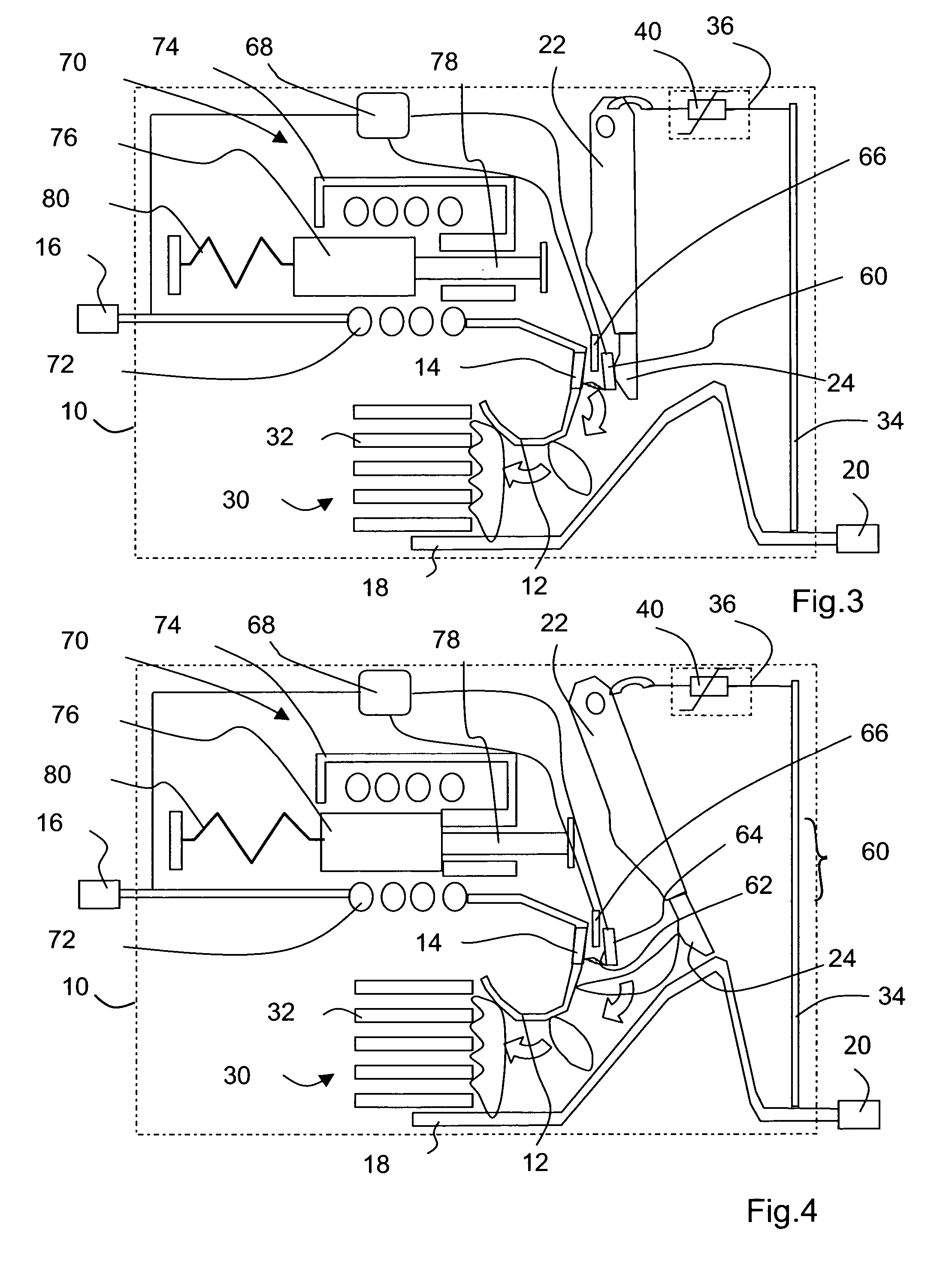
[0032] In FIGS. 1 and 2 a protection device against voltage surges according to the invention is represented. Inside a molded case 10 made of insulating synthetic material there are arranged a first connecting electrode 12 provided with a fixed contact 14 and connected to a first connecting pad 16, a second connecting electrode 18 connected to a second connecting pad 20, and a mobile transfer electrode 22 provided with a mobile contact 24, pivoting around a fixed axis 26 from an operating position represented in FIG. 1, ensuring contact between the two contacts 14, 24, to a switching position represented in FIG. 2, in which position the mobile electrode 22 is close to the second connecting electrode 18. The two connecting electrodes 12, 18 are located at a distance from one another, and bound the inlet of an arc chute 30 equipped with deionizing fins 32.

[0033] The second connecting pad 20 is also connected to the mobile electrode 22 by means of a circuit branch 34 containing an elec...

fourth embodiment

[0050] The device differs from the previous embodiments essentially by the fact that it is provided with an opening mechanism 90 of the type that is usually to be found in circuit breakers. Such a mechanism comprises an upper rod 92 and a lower rod 94 forming a toggle joint 96 connecting a catch 98 to an electrode support bar 100, supporting the mobile electrode 22 by means of a contact pressure spring 102. The catch 98 pivots around a fixed axis 104 and is retained by a latch 106 in a latching position. A handle 108 pivoting around a fixed geometric axis 110 is connected to the swivel-pin 112 of the toggle 96 by means of an energy storage spring 114. An electromechanical relay 116 controls the position of the latch according to electrical parameters such as the intensity of the current flowing in the electric dipole 36 as a function of time. In the closed position of the mechanism, in FIG. 6, the catch 98 is in the latched position and the mobile electrode 22 is in the operating p...


PUM


Abstract

A protection device against voltage surges, connected between an electric line and earth, comprises a first connecting electrode, a second connecting electrode and a mobile switching electrode for switching between an operating position, in contact with the first connecting electrode, and a switching position, close to the second connecting electrode. An electric dipole, comprising for example a variable resistor and / or a spark arrester, connects the mobile electrode to the second connecting electrode. The mobile electrode can be moved by a mechanism, an electromechanical relay and / or a magnetic circuit performing repulsion when the current intensity becomes very high. Separation of the electrodes produces an arc which limits the current flowing in the dipole then, by switching on the second connecting electrode, performs disconnection of the dipole from the circuit thus ensuring protection thereof.

Description

BACKGROUND OF THE INVENTION [0001] The invention relates to a device designed to divert an electric current wave to earth when the voltage of a line exceeds a given threshold. STATE OF THE PRIOR ART [0002] In the document DE 32 28 471 there is described a device of this type formed by two parallel circuit branches arranged between an input terminal connected to a line and an output terminal connected to earth. One of the branches comprises a spark arrester, the other branch comprising a variable resistor. It is known that the spark arrester has a higher response time than the variable resistor. When a small voltage surge characteristic of a lightning flash situated a long distance from the device occurs between the terminals, the variable resistor is turned on in a few nanoseconds and the current flows without the spark arrester being put into operation, as the ignition voltage of the spark arrester is never reached. When a large voltage surge characteristic of a lightning flash in ...

Claims


Application Information

Patent Timeline
IPC IPC(8): H02H9/06H01H83/10H02H9/04
CPCH01H83/10H02H9/042H01H2071/044
Inventor DOMEJEAN, ERICDICONNE, ROBERT
Owner SCHNEIDER ELECTRIC IND SAS
Learn More