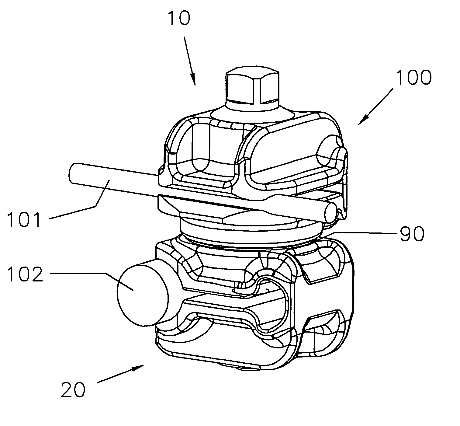
Clamping and articulation element
a technology of articulation element and articulation cavity, which is applied in the direction of invalid friendly devices, prostheses, osteosynthesis devices, etc., can solve the problem of insertion of rod-shaped elements into the receiving cavity, and achieve the effect of simple manner
- Summary
- Abstract
- Description
- Claims
- Application Information
AI Technical Summary
Benefits of technology
Problems solved by technology
Method used
Image
Examples
first embodiment
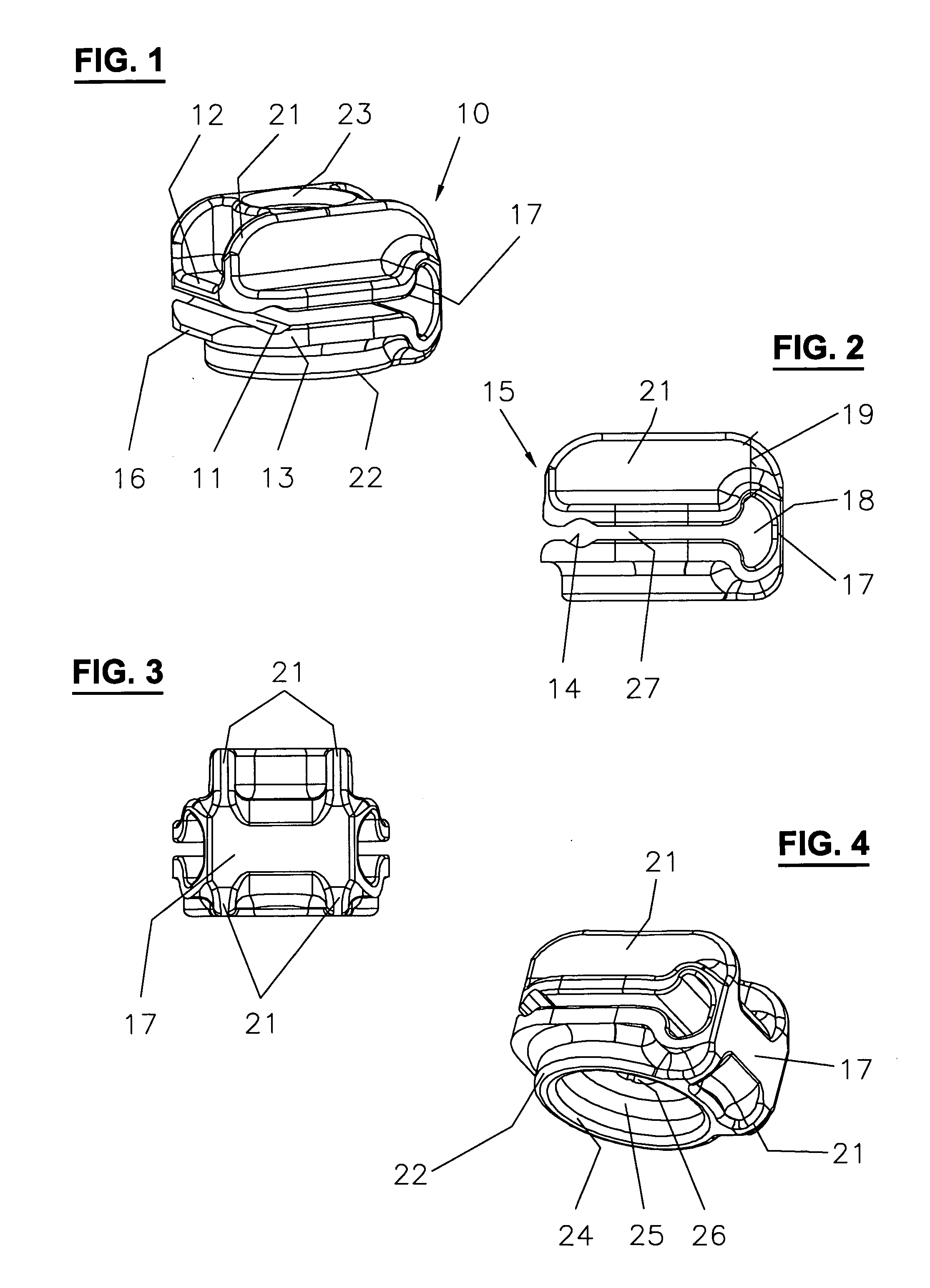
[0053] FIGS. 1 to 4 show a clamping element 10 per the invention. FIG. 1 shows a perspective view at an angle from the top. The clamping element 10 has two opposing cavities and one cavity 11 to receive clamping jaws 12 and 13 forming a rod-shaped element. On their free ends 15, clamping jaws 12 and 13 each have a transversely running grooves 14, which together clamp to form the cavity 11. At the free ends 15, the outer edges 16 of the side facing clamping jaws 12 and 13 are slanted to simplify the lateral insertion of a rod-shaped element. Across from the cavity 11 and the free ends 15, a hinge 17 is arranged, connecting clamping jaws 12 and 13 in a single piece. When the clamping element 10 is intended for a rod with 4 to 6 millimeters in diameter, the opening at the free ends has a diameter of, for instance, 2 millimeters in a resting position.
[0054] When clamping element 10 is made of synthetic material, hinge 17 is a thinned material section, followed by a recess 18 running lat...
second embodiment
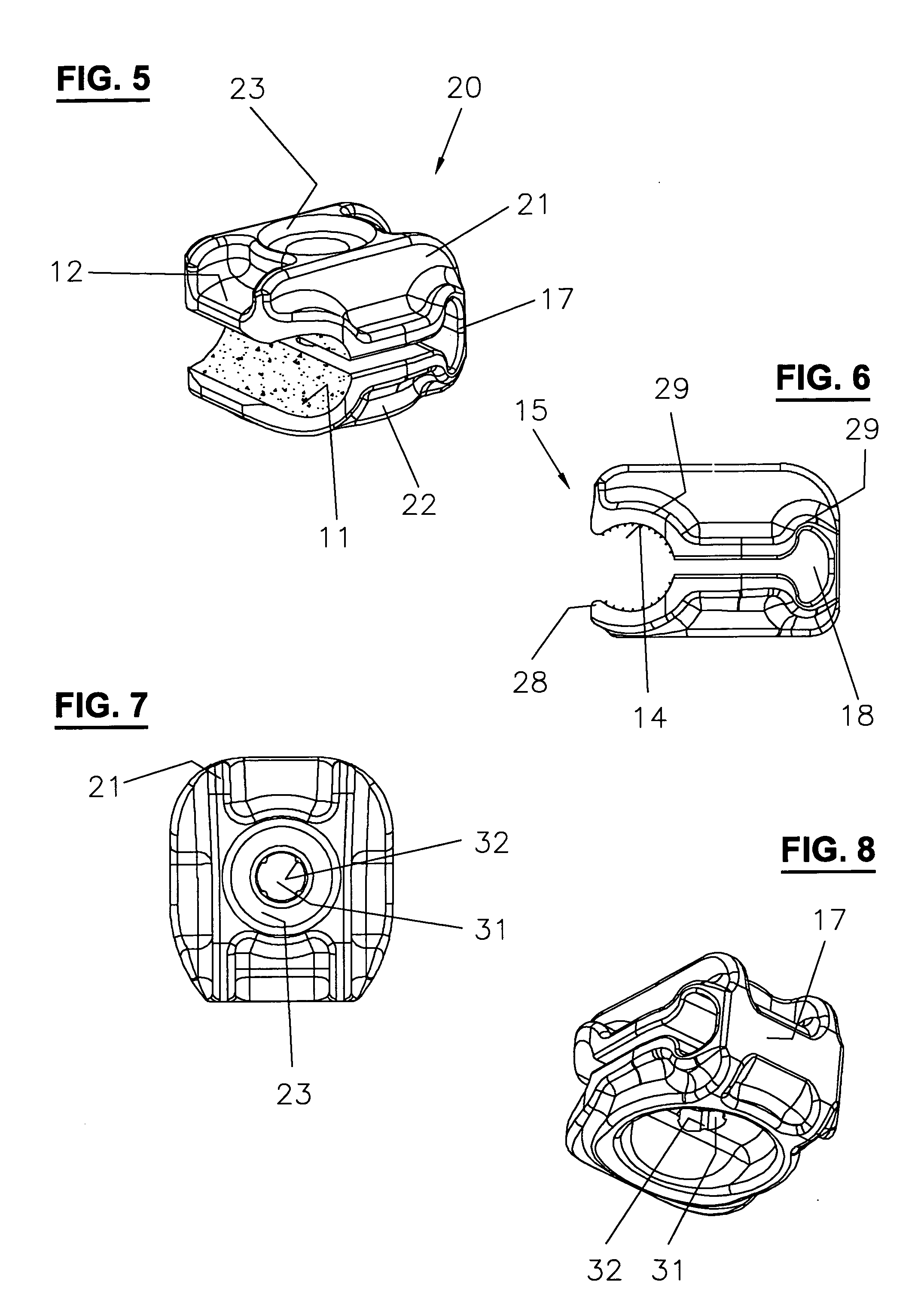
[0058]FIG. 5 to 8 show a clamping element 20 according to the invention. The same characteristics are identified with the same reference numerals. FIG. 5 shows a perspective view, at an angle from above. The only difference between the two clamping elements 10 and 20 per FIG. 1 and FIG. 5 is that clamping element 20 is intended to receive a rod-shaped element larger in diameter. This means that the grooves 14 are larger. The center axis of cavity 11, however, is still at the same height of slit 27. Here, the grooves 14 are so large that the free ends 15 form only a rounded area 28 to the outside, which simplifies a lateral insertion of rods. Like the fender 29 the groove 14, respectively the recess 18, is spanned to ensure the rigidity of the clamping element 20 (or 10). If the clamping element 20 is intended for a rod with a diameter of 12 millimeters, the opening at the free ends has a diameter of, for instance, 9 millimeters in a resting position.
[0059]FIG. 6 and 8 again show cla...
PUM
 Abstract
Description
Claims
Application Information
 - R&D
- Intellectual Property
- Life Sciences
- Materials
- Tech Scout
- Unparalleled Data Quality
- Higher Quality Content
- 60% Fewer Hallucinations
Browse by: Latest US Patents, China's latest patents, Technical Efficacy Thesaurus, Application Domain, Technology Topic, Popular Technical Reports.
© 2025 PatSnap. All rights reserved.Legal|Privacy policy|Modern Slavery Act Transparency Statement|Sitemap|About US| Contact US: help@patsnap.com


