
Programmable wallbox dimmer

a programmable wallbox and dimming technology, applied in the direction of electric variable regulation, process and machine control, instruments, etc., can solve the problem of accidental implementation of protected presets

Active Publication Date: 2006-01-19
LUTRON TECH CO LLC
View PDF12 Cites 71 Cited by
  • Summary
  • Abstract
  • Description
  • Claims
  • Application Information

AI Technical Summary

Benefits of technology

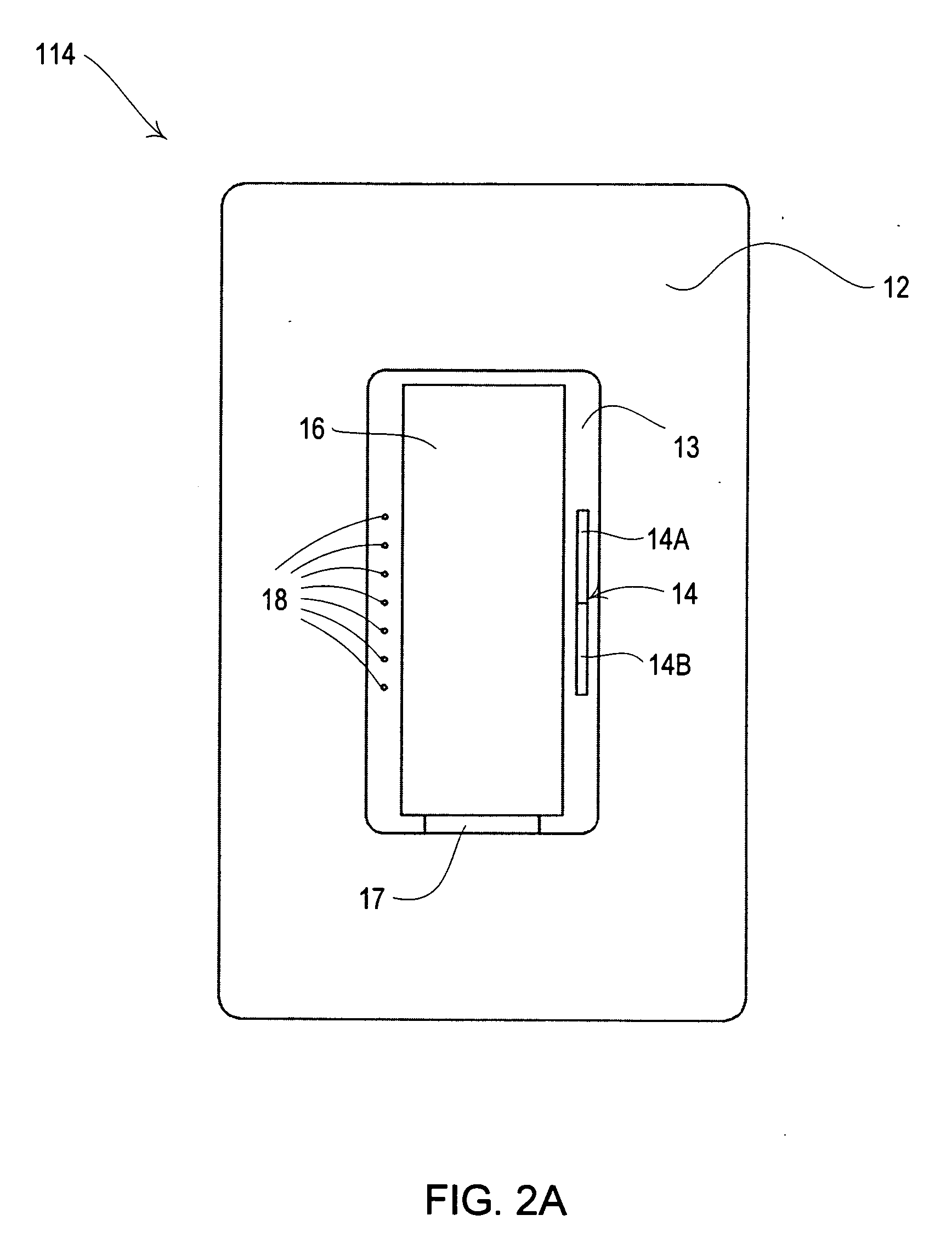
[0023] The invention provides a programmable lighting control device that controls a light intensity level of at least one lamp. The lighting control device may include a user-actuatable intensity selector, a user-actuatable control switch, a user-actuatable air gap controller, and a microcontroller operatively coupled to the intensity selector, the control switch, and the air gap controller. In a normal operational mode, the intensity selector enables a user to select a desired intensity level between a minimum intensity level and a maximum intensity level, the control switch enables the user to turn the lamp on and off, and the air gap controller enables the user to disrupt power to the lighting control device.

Problems solved by technology

It has been found that, in such a dimmer, protected preset may be accidentally implemented.

Method used


Image

  • Programmable wallbox dimmer
  • Programmable wallbox dimmer
  • Programmable wallbox dimmer

Examples


first embodiment

[0081] In the invention, the feature value may be set (i.e., stored in memory 137) as the user cycles through the prescribed values. Thus, the user may select a value for the feature by merely scrolling through the list of prescribed values until the desired value is highlighted (e.g., the LED associated with the desired value is blinking). Also, for certain features, e.g., protected preset, the dimmer may also be programmed to control the intensity of the lighting load 116 as the user cycles through the prescribed values. Thus, the user may see the effect the currently presented value will have on dimmer performance.

[0082] In an alternate embodiment, the microcontroller 132 stores the currently presented value (i.e., the value that is associated with the LED that is blinking when the rocker is released) after the user releases the raise-intensity actuator 14a or the lower-intensity actuator 14b for a period of time. Thus, the user can scroll through the values without changing the ...

third embodiment

[0083] In a third embodiment, the value of the feature does not change in memory 137 unless the toggle actuator 16 is selected within a prescribed period of time from the time at which the raise-intensity actuator 14a or the lower-intensity actuator 14b is released.

[0084] If a feature is defined by more than one variable parameter, it might be desirable to provide another mode presenting a list of user-programmable parameters similar to the feature selection mode. According to an aspect of the invention, any or all of these variable parameters may be programmed. That is, if the user selects a feature in the feature selection mode that is defined by more than one parameter, then a parameter selection mode (rather than the value selection mode) may be entered wherein each of one or more LEDs is associated with a respective variable parameter that defines the selected feature. The user may scroll through the parameters of the parameter selection mode and select a parameter to program. ...


PUM


Abstract

A programmable wallbox dimmer is disclosed. Upon entering a programming mode, the dimmer presents a main menu from which the user may select one or more features to program. The user may scroll through a list of programmable features by actuating the dimmer's raise / lower intensity actuator. The user may select a highlighted feature by actuating the dimmer's control switch. The dimmer may enter a value selection mode that is associated with the selected feature. In the value selection mode, the user may scroll through a list of features that define the selected feature by actuating the dimmer's raise / lower intensity actuator. The user may select a value for the selected feature. The selected value may be stored in the dimmer's memory.

Description

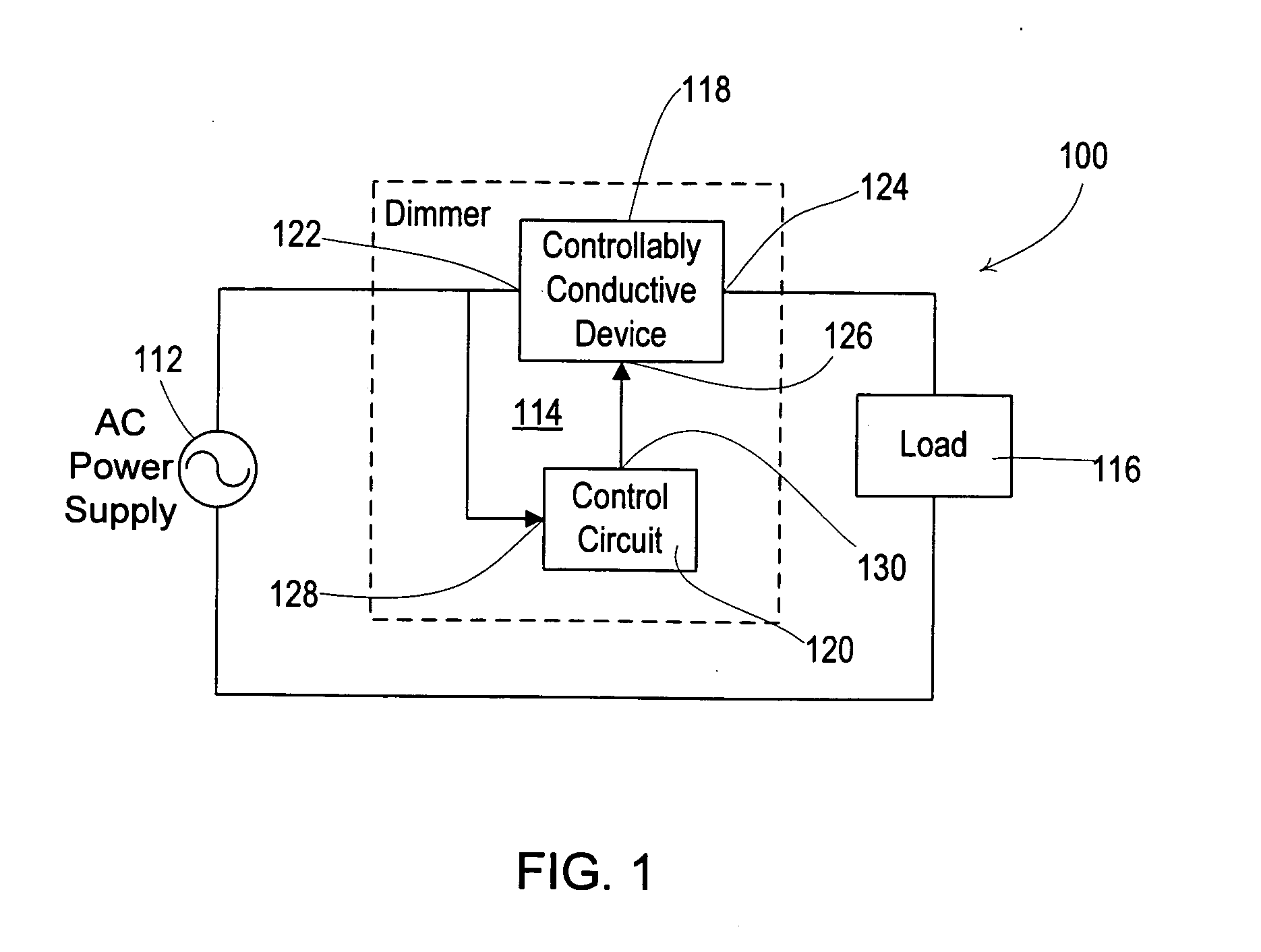
FIELD OF THE INVENTION [0001] Generally, the invention relates to lighting control devices. More particularly, the invention relates to programmable wallbox dimmers. BACKGROUND OF THE INVENTION [0002]FIG. 1 depicts a typical dimmer circuit 100 comprising a source of electrical energy or power supply 112, a dimmer 114, and a lighting load 116. The lighting load 116 may be a lamp set comprising one or more lamps adapted to be connected between the hot and neutral terminals of a standard source of electrical energy. The lamp set may include one or more incandescent lamps and / or other lighting loads such as electronic low voltage (ELV) or magnetic low voltage (MLV) loads, for example. [0003] The power supply 112 supplies an electrical waveform to the dimmer 114. The dimmer regulates the delivery of electrical energy from the power supply 112 to the lighting load 116. The dimmer 114 may include a controllably conductive device 118 and a control circuit 120. The controllably conductive de...

Claims


Application Information

Patent Timeline
IPC IPC(8): H05B37/02
CPCH05B37/0209H05B39/044H05B37/0245H05B47/175H05B47/185H05B47/17H05B47/165
Inventor MCDONOUGH, BRIDGETZAHARCHUK, WALTER S.BLAIR, EDWARD J.
Owner LUTRON TECH CO LLC
Learn More