
Microstructures using carbon fiber composite honeycomb beams

a carbon fiber composite and honeycomb beam technology, applied in the direction of generator/motor, toy aircraft, ornithopter, etc., can solve the problems of difficult construction and low resonant frequency

Inactive Publication Date: 2006-01-12
RGT UNIV OF CALIFORNIA
View PDF10 Cites 36 Cited by
  • Summary
  • Abstract
  • Description
  • Claims
  • Application Information

AI Technical Summary

Problems solved by technology

This has drawbacks of having high inertias, thus lowering the resonant frequency, as well as being difficult to construct.

Method used


Image

  • Microstructures using carbon fiber composite honeycomb beams
  • Microstructures using carbon fiber composite honeycomb beams
  • Microstructures using carbon fiber composite honeycomb beams

Examples


Embodiment Construction

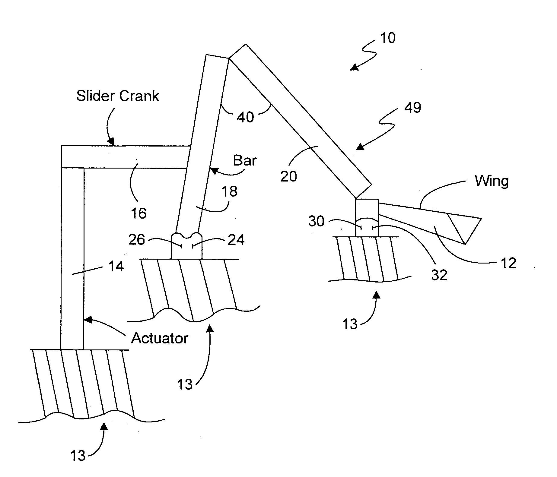
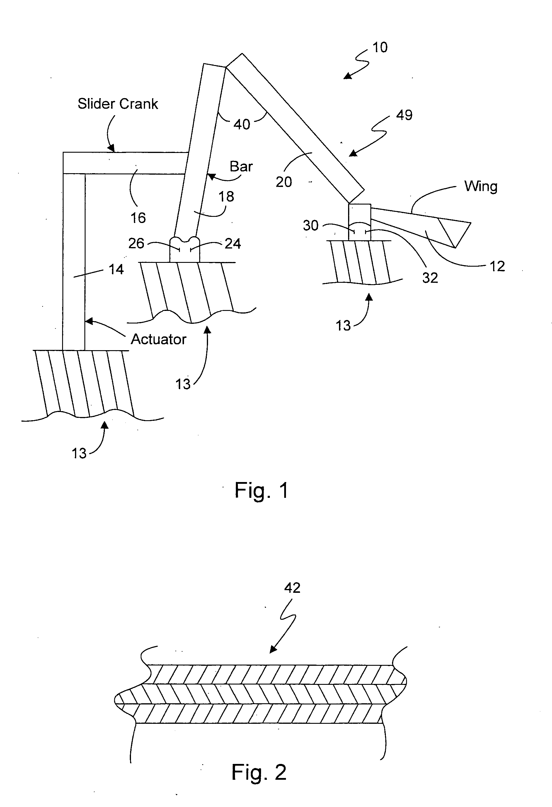
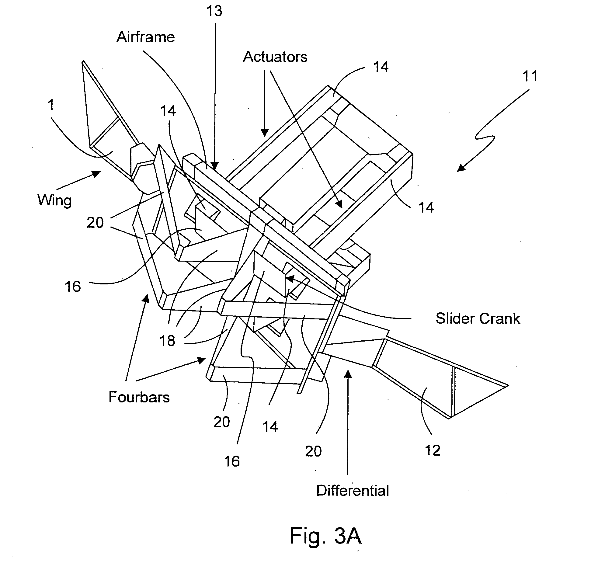
[0007] Embodiments of the present invention also provide a drive assembly for a wing of a micromechanical flying insect. The drive assembly includes a honey comb structure, and an actuator including a piezoelectric material and a bonding layer. The actuator comprises a single crystal piezoelectric or an amorphous piezoelectric layer.

[0008] Embodiments of the present invention further also provide a method for flying a micromechanical flying insect comprising moving a wing with a drive assembly having a stiffness to weight ratio greater than about 16×1010 N / mKg. The drive assembly comprises a honeycomb structure.

[0009] These provisions together with the various ancillary provisions and features which will become apparent to those artisans possessing skill in the art as the following description proceeds are attained by devices, assemblies, systems and methods of embodiments of the present invention, various embodiments thereof being shown with reference to the accompanying drawings...


PUM


Abstract

A drive assembly for a wing of a micromechanical flying insect. The drive assembly comprises a honey comb structure. A method for flying a micromechanical flying insect comprising moving a wing with a drive assembly having a stiffness to weight ratio greater than about 16×1019 N / mKg.

Description

[0001] This application claims the benefit of U.S. Provisional Application 60 / 470,456, filed May 14, 2003, and fully incorporated herein by reference thereto.ACKNOWLEDGMENT OF GOVERNMENT SUPPORT [0002] This invention was made with Government support under Grant (Contract) No. ECS-9873474 awarded by NSF, and N00014-98-1-0671 awarded by ONR MURI. The Government has certain rights to this invention.BACKGROUND OF THE INVENTION [0003] 1. Field of the Invention [0004] This invention is related in general to micromechanical flying insect (MFI) devices. More specifically, embodiments of the present invention provide a drive assembly for a wing of a MFI. [0005] 2. Description of the Background Art [0006] Micro flapping structures such as are used in the MFI are required to produce large displacements at high resonant frequencies, while performing complex kinematic patterns. The MFI wings must be capable of independently going through a wing stroke of 120°, while being able to rotate 90° at a...

Claims


Application Information

Patent Timeline
Patent Type & Authority Applications(United States)
IPC IPC(8): B64C33/02B64C33/00B64C39/02B81B
CPCB64C33/02B64C2201/025B64C39/028B64U10/40B64U10/80B64U20/65
Inventor WOOD, ROBERT
Owner RGT UNIV OF CALIFORNIA
Learn More