Radio signal relaying apparatus
- Summary
- Abstract
- Description
- Claims
- Application Information
AI Technical Summary
Problems solved by technology
Method used
Image
Examples
first embodiment
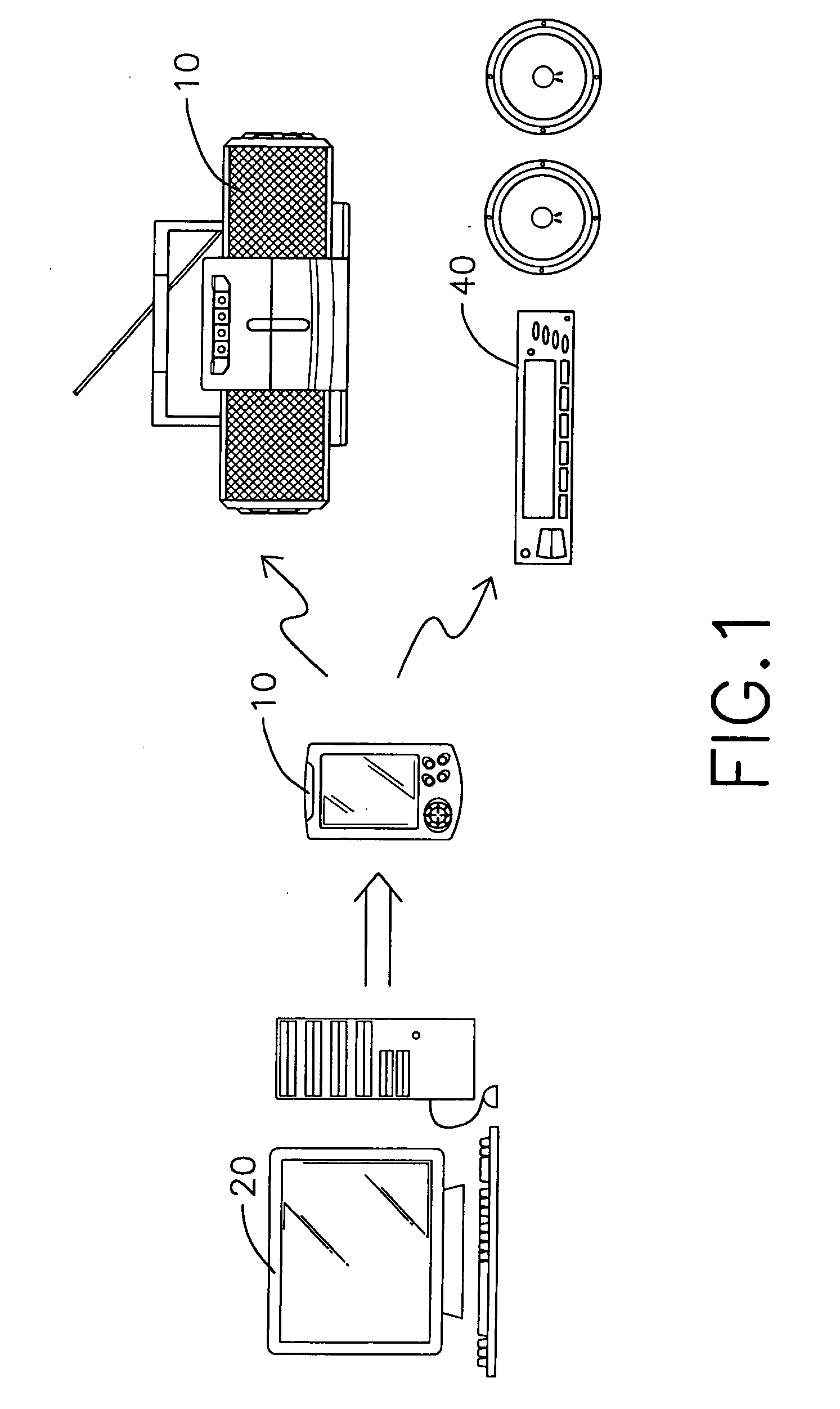
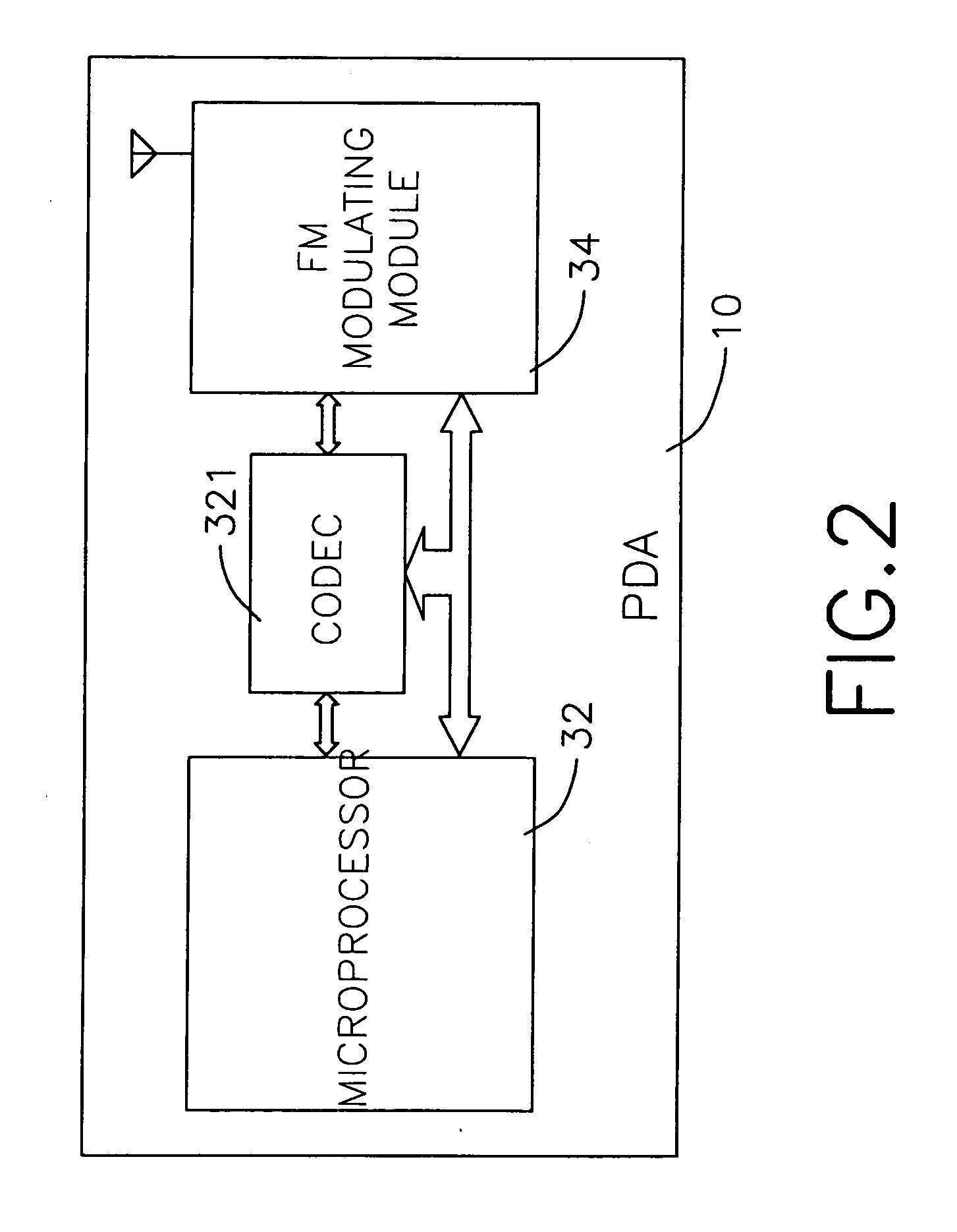
[0018] With reference to FIG. 2, the present invention is implemented by the PDA (10) having a microprocessor (32), an FM modulating module (34) and a coder-decoder (CODEC) (321) connected between the microprocessor (32) and the FM modulating module (34). The music files stored in the PDA are digitized data. Therefore before transmitting the music files, the microprocessor (32) firstly retrieves the music files and outputs these files to the CODEC (321). The CODEC (321) then converts the digital data to analog format and sends the analog data to the FM modulating module (34). Based on the set frequency value, the microprocessor (32) controls the FM modulating module (34) to modulate the analog data to become radio signals and to transmit the radio signals thus allowing the radio receiving device (40) to receive and play the radio signals.
second embodiment
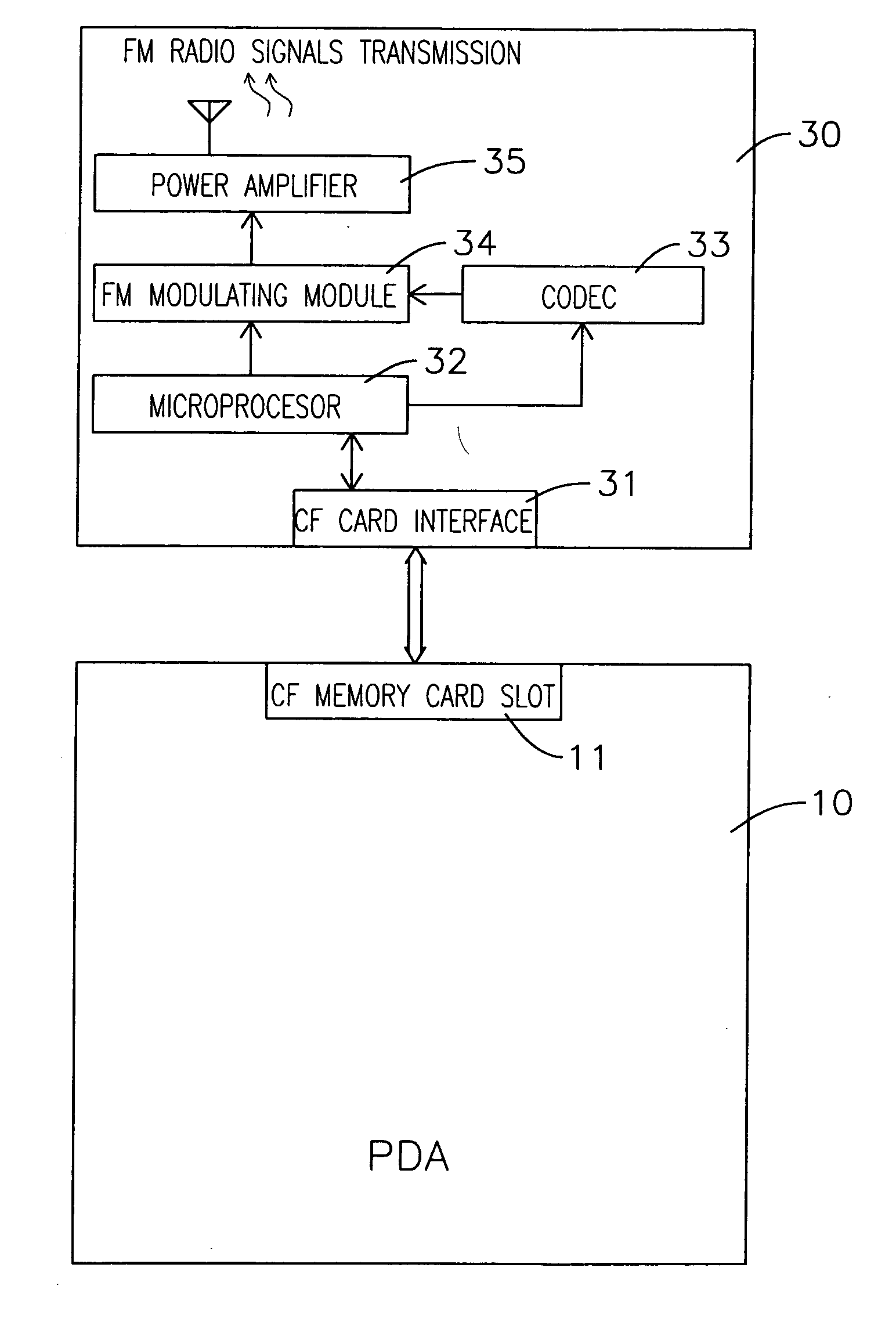
[0019] With reference to FIG. 3, the present invention comprises a PDA (10) having a CF memory card slot (11) and a wireless modulating module (30) electrically connected to the CF memory card slot (11). The wireless modulating module (30) comprises a linking interface such as a CF card interface (31), a microprocessor (32), a CODEC (33), an FM modulating module (34) and a power amplifier (35). The CF card interface (31) correspondingly connects to the CF memory card slot (11). The microprocessor (32), which is connected to FM modulating module (34) and the CODEC (33), retrieves the digital music files from the PDA (10) through the CF card interface (31) and obtains the set frequency parameter that applies for signal modulating. The CODEC (33) receives the digital music files from the microprocessor (33) and converts the files to analog data. The analog data is further output to the FM modulating module (34). The FM modulating module (34) modulates the analog data with the set frequ...
third embodiment
[0021] With reference to FIG. 4, the present invention is substantially the same as that of FIG. 3. A change made to the embodiment is that the PDA (10) uses a USB port (12) to electrically connect to the wireless modulating module (30). Accordingly, the wireless modulating module (30) forms a USB interface (36) that is preferably made like a USB connector to correspondingly connect to the USB port (12).
[0022] Yet another embodiment is shown in FIG. 5, wherein the PDA (10) provides an SD memory card slot (14) to electrically link to an SD card interface (38) of the wireless modulating module (30). Similarly, the appearance of the wireless modulating module (30) is preferably constructed like an SD memory card.
[0023] With reference to FIG. 6, the PDA (10) uses a serial port (13) to electrically connect to a serial port (37) of the wireless modulating module (30). The serial ports (13)(37) could be any known standard, such as the RS-232 communication protocol. It is noted that since ...
PUM
 Abstract
Description
Claims
Application Information
 - R&D
- Intellectual Property
- Life Sciences
- Materials
- Tech Scout
- Unparalleled Data Quality
- Higher Quality Content
- 60% Fewer Hallucinations
Browse by: Latest US Patents, China's latest patents, Technical Efficacy Thesaurus, Application Domain, Technology Topic, Popular Technical Reports.
© 2025 PatSnap. All rights reserved.Legal|Privacy policy|Modern Slavery Act Transparency Statement|Sitemap|About US| Contact US: help@patsnap.com


