
Yo-yo bearing member

a bearing member and yo-yo technology, applied in the field of yo-yos, can solve the problems of yo-yo play type, difficulty in setting a wide enough string gap to accommodate a plurality of lays of string, premature return of the yo-yo to the player's hand, etc., to achieve the effect of economic and light weight, effective snaring, and surface coefficient of friction

Inactive Publication Date: 2005-12-29
OSULLIVAN BRENDON
View PDF7 Cites 15 Cited by
  • Summary
  • Abstract
  • Description
  • Claims
  • Application Information

AI Technical Summary

Benefits of technology

"The invention is a bearing member for a yo-yo that helps to center the string on the bearing and allows for advanced string trick play. The bearing has a concave surface with a variable depth and a smooth transition between the inner and outer surfaces. The bearing can be fitted with a frictional surface to interact with the yo-yo clutch mechanism. The invention also provides a variety of string-gap settings to accommodate different player levels."

Problems solved by technology

One of the limitations to this type of yo-yo play was the premature return of the yo-yo to the player's hand due to snagging of the string on the “starburst” pattern of raised ridges on the medial faces of the yo-yo halves.
Conversely, another limitation to this type of play was the difficulty of setting a wide enough string gap to accommodate a plurality of lays of string, and yet having the response capability to snare and rewind the string so as to return the yo-yo to the player's hand on demand.
A further limitation was that, at extremely wide string gap settings, the axial extension of the cylindrical outer surface of the roller bearing was insufficient to maintain the string in a central position with respect to the medial faces of the yo-yo halves, to prevent bearing slap and to prevent the string becoming snagged between the bearing and the said medial faces.
This is the result of having to provide support structure, and the only engineering way, due to limitations imposed by the known effective string snaring capacity of an integral starburst response system, is to provide structure by increasing the bearing outside diameter that is at right angles to the axle.
An outside diameter of 30% plus effectively makes the task of producing a high performance yo-yo impossible.

Method used


Image

  • Yo-yo bearing member
  • Yo-yo bearing member
  • Yo-yo bearing member

Examples


Embodiment Construction

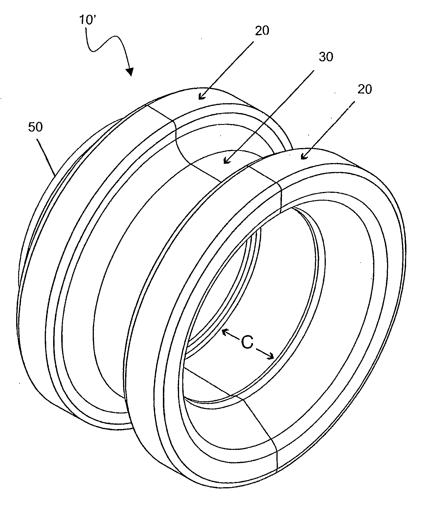
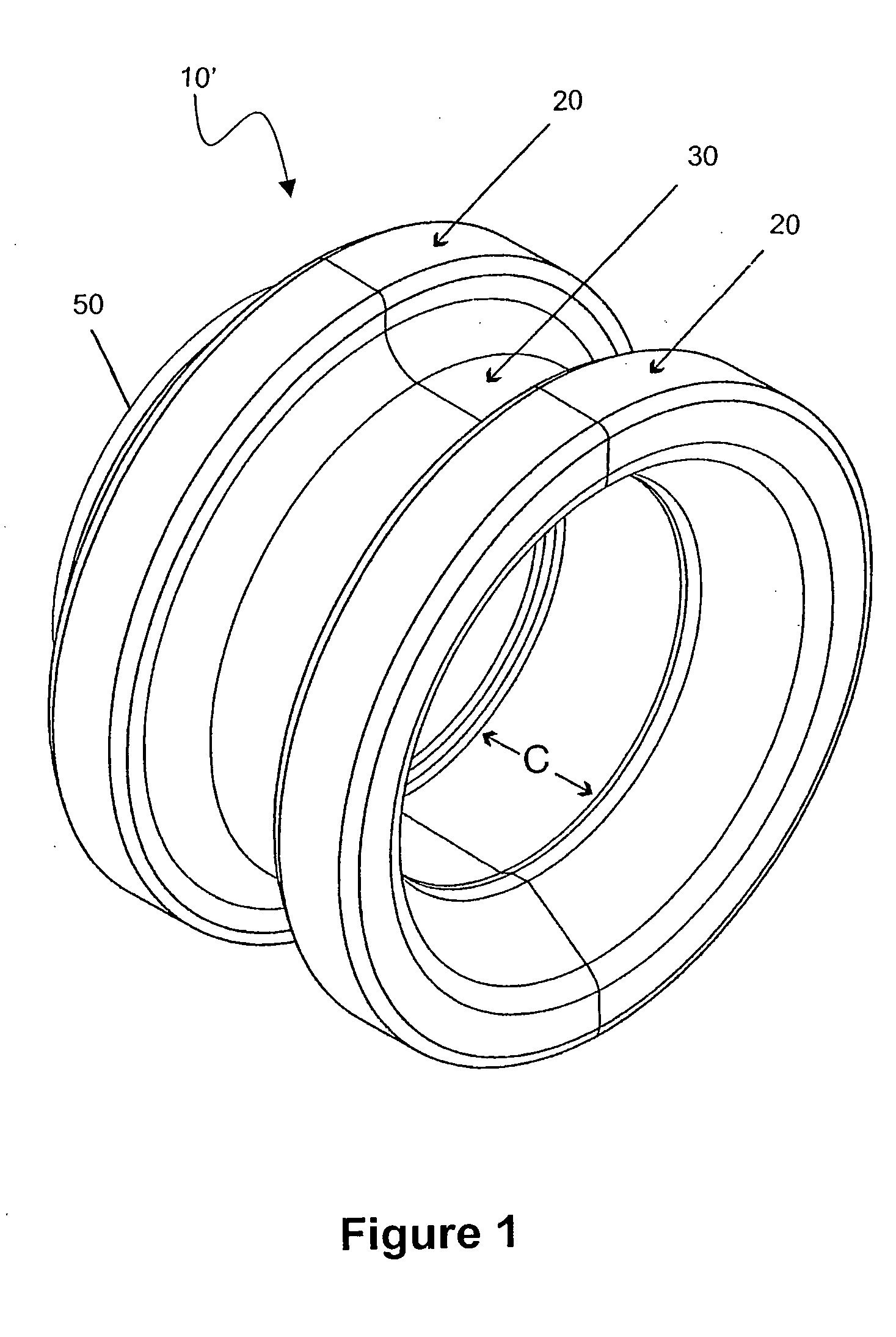
[0042] With reference to the drawings, wherein like numerals represent like parts, FIG. 1 shows an isometric view of a bearing sleeve 10 or ball-bearing outer race of an embodiment of the present invention wherein the outer quasi-cylindrical face 20 is provided with a broad concave shaped outer surface 30 able to accept more than one lay of string. The distance C is the axial width of a contained bearing 40 in the case of a bearing sleeve, or of the inner race and the ball-race with dust-covers in the case of being a ball-bearing outer race.

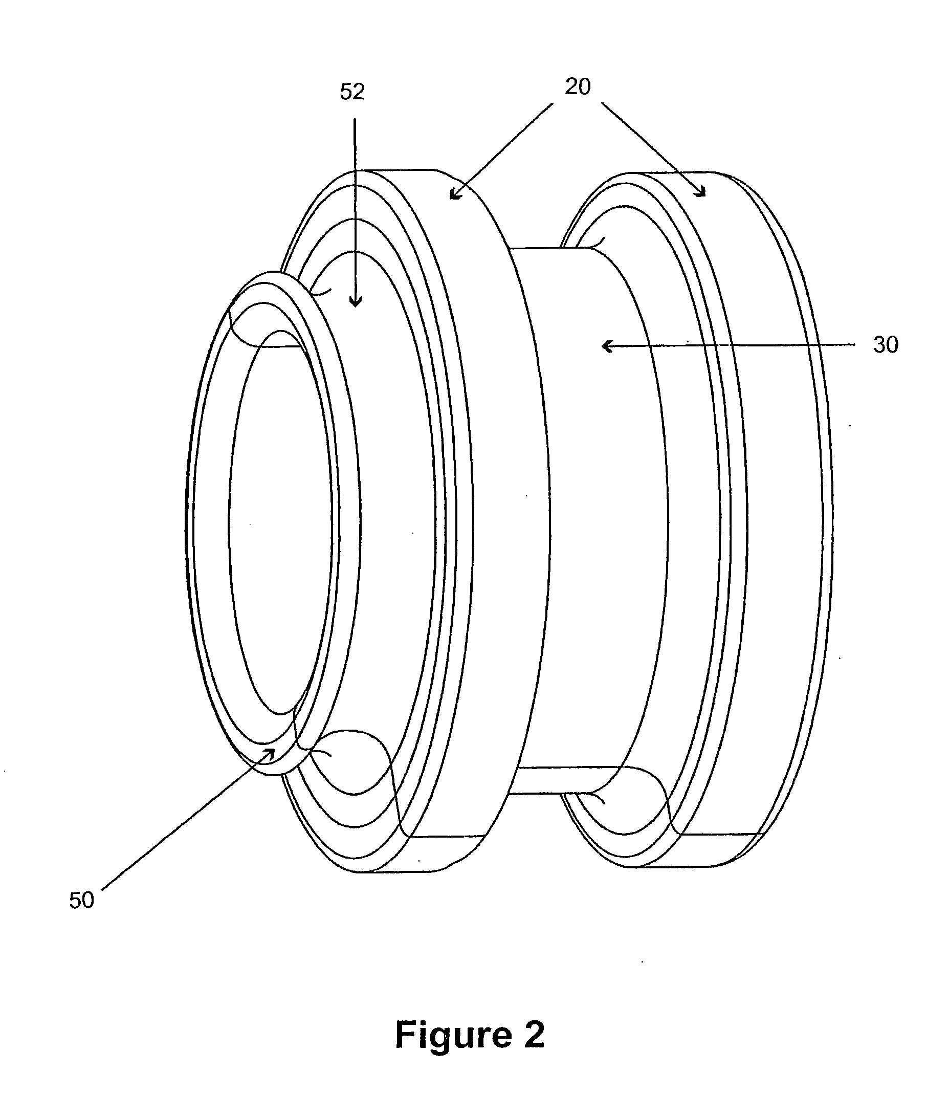
[0043]FIG. 2 shows another view of the same embodiment, rotated horizontally through some 45 or so degrees from the previous figure, which shows the extension 50 of the outer surface 20 to accommodate a friction braking member (not shown) to be seated in groove 52.

[0044] Another embodiment of a bearing sleeve 10 is illustrated in FIGS. 3 and 4.

[0045] With reference to FIGS. 5 and 6, a yo-yo 100 which employs the bearing sleeve 10 includes yo-y...


PUM


Abstract

The invention relates to yo-yos and in particular high-performance ball- or roller-bearing yo-yos capable of extremely wide string-gap settings suitable for “new school” yo-yo tricks. The present invention addresses the need to center the yo-yo string on the bearing or bearing sleeve along the axial extension of the outer surface of the yo-yo bearing or bearing sleeve or in relation to the effective “string gap” between the opposed inner faces of the two yo-yo halves. The present invention also provides an effective and economical string-bearing surface able to span the wider string gap required by “new school” styles and modes of play. The present invention enables the variable stacking of successive lays of string either side of the securing loop during complicated yo-yo string trick routines.

Description

CROSS-REFERENCE TO RELATED APPLICATION [0001] This application is a continuing application of PCT Application No. PCT / AU2004 / 001176 filed Aug. 31, 2004.FIELD OF THE INVENTION [0002] The invention relates to yo-yos and in particular high-performance ball- or roller-bearing yo-yos capable of extremely wide string-gap settings suitable for “new school” yo-yo tricks. The rapid emergence of new skills amongst practitioners has prompted the invention of new types of yo-yos; the present invention resolves many of the difficulties involved in producing such yo-yos. BACKGROUND OF THE INVENTION [0003] The introduction of ball-bearing yo-yos in the 'nineties saw a quantum leap in the possibilities for new yo-yo tricks and techniques due to the enormously extended spin times afforded by ball- and roller-bearing yo-yos. These techniques, referred to as “new school”, involve the elaboration of many lays of string between the spinning yo-yo halves—as many as five or six lays as the string is doubl...

Claims


Application Information

Patent Timeline
Patent Type & Authority Applications(United States)
IPC IPC(8): A63H1/30
CPCA63H1/30
Inventor O'SULLIVAN, BRENDON
Owner OSULLIVAN BRENDON
Learn More