
Flexible mirror device for a vehicle

a mirror device and flexible technology, applied in the field of mirror devices, can solve problems such as limiters experienced by drivers who are too short, and achieve the effect of clearer visibility, reliable and safe driving

Inactive Publication Date: 2005-12-29
LEE YUN JOO +3
View PDF11 Cites 4 Cited by
  • Summary
  • Abstract
  • Description
  • Claims
  • Application Information

AI Technical Summary

Benefits of technology

[0004] The present invention is contrived to overcome the conventional disadvantages. Accordingly, it is an objective of the present invention to provide a flexible, detachable and portable mirror device for a vehicle. Another objective is to provide a mirror device for a vehicle that enables a driver to change lanes and make turns with clearer visibility of rear views. A further objective is to enable a senior citizen and a relatively short person to make a reliable and safe driving.
[0006] For a better performance, the internal portion may be a driver's window glass of the vehicle or a windshield of the vehicle. The mirror is formed of a convex glass lens, and the base comprises a plastic suction cup.
[0008] Advantages of the present invention are numerous in that: (1) the elongate member secures controllable adjustability of the mirror device so that the mirror can be controllably adjusted to an aerial position depending on safety degree or terrain of the driving area, thereby maximizing usability and product reliability; (2) the detachable attachment mechanism of the base or the clamp of the mirror device enables a driver to easily reposition the mirror device, for example, from a side window to the dashboard or to a ventilation port louver, within the vehicle, thereby enhancing instant availability and subsequent user's satisfaction; and (3) the combination of the belt rings and the miniature dumbbells is elevated to flexibility and portability of the mirror device and further elevated to driving safety and subsequent marketability.

Problems solved by technology

However, limitations are experienced among drivers who are too short to look over the headrest of the driver's seat and among senior citizens whose physical slowness may trigger mishaps on the road.

Method used


Image

  • Flexible mirror device for a vehicle
  • Flexible mirror device for a vehicle
  • Flexible mirror device for a vehicle

Examples


Embodiment Construction

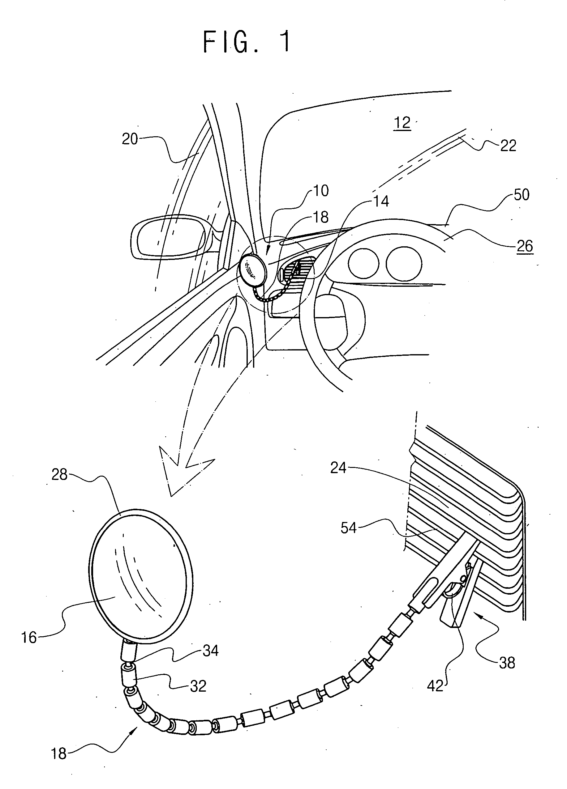
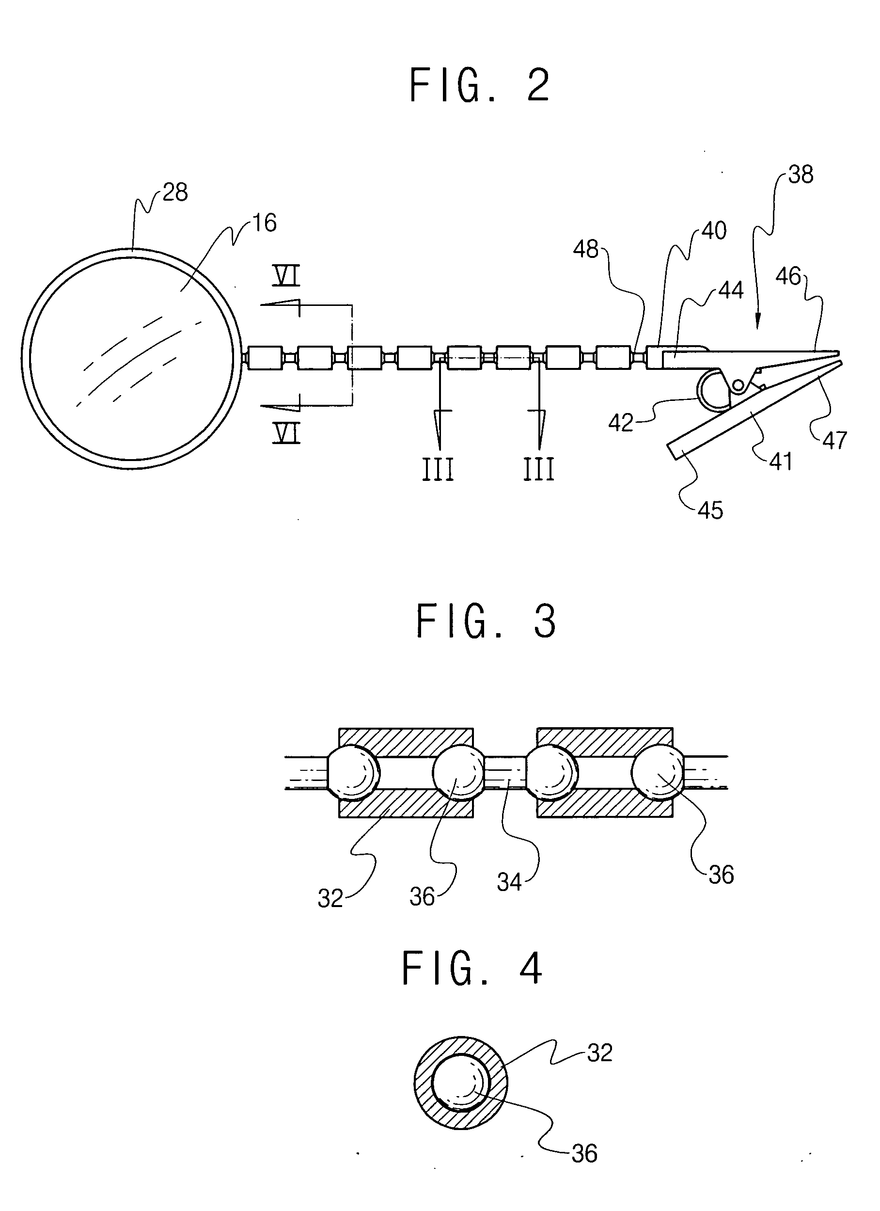
[0017] FIGS. 1 to 4 each show construction and installation according to a preferred embodiment of a mirror device 10 for a vehicle 12. FIGS. 5 and 6 each show specific application of the mirror device 10 within the vehicle 12. FIG. 7 shows a mirror device for a vehicle according to another embodiment of the vehicle mirror device 10. Here, the vehicle 12 denotes, but not limited to, a land vehicle with internal combustion engines.

[0018] As shown therein, the vehicle mirror device 10 comprises a base 14, a mirror 16 and a substantially elongate member 18. The base 14 is detachably attached to an internal portion 20, 22, 24 of the vehicle. Preferably, the internal portion 20, 22, 24 is provided within a viewable range from a driver (not shown) sitting behind a steering wheel 26 of the vehicle 12. It is recommended that the mirror 16 be attached to a mirror pad 28.

[0019] In order to facilitate the detachable attachment of the mirror device 10 within the vehicle 12, the base 14 may be...


PUM


Abstract

A mirror device for a vehicle comprising a base detachably attached to an internal portion of the vehicle, within a viewable range from a driver sitting behind a steering wheel of the vehicle, a mirror attached to a mirror pad, and a substantially elongate member connecting the mirror pad to the base. The elongate member is formed of belt rings and miniature dumbbells alternately interlinked with the belt rings such that each ball of the dumbbells is rotatably caught in a corresponding one of the belt rings, whereby the elongate member is controllably adjustable to one of an infinite number of aerial settings thereof so that the mirror is subsequently displaced to an aerial position desired by the driver.

Description

BACKGROUND OF THE INVENTION [0001] The present invention relates to a mirror device for a safe driving of a vehicle. More particularly, the present invention relates to a mirror device for a vehicle, enabling a vehicle driver to conveniently see through the so-called dead zone while improving a rearview visibility of the driver. [0002] As is well known, vehicle drivers rely on side mirrors and rearview mirrors to change lanes on the road, to secure driving safety, to effectuate defensive driving and to prevent other hazardous incidents open to all the vehicle drivers day in and day out. The side mirrors are preferred by most drivers when changing lanes and making turns. In order to secure safe driving and decrease road incidents, what is strongly recommended by governmental vehicle departments is a regulation that commands a driver look over the shoulder to check clearance of the lane to which the driver wants to move. However, limitations are experienced among drivers who are too s...

Claims


Application Information

Patent Timeline
IPC IPC(8): B60R1/04B60R1/08G02B7/182G02B17/00
CPCB60R1/04G02B7/1824B60R1/08
Inventor LEE, YUN JOOKIM, JAY JONG-SUKKIM, YONG JONGKIM, YOUNG OK
Owner LEE YUN JOO
Learn More