Auto-pumping unit for bag-valve-mask resuscitator

a bag-valve mask and auto-pumping technology, which is applied in the field of medical first-aid equipment, can solve the problems of affecting the patient's recovery, the inability of the first-aid person to operate other first-aid equipment or take care of the patient, and the difficulty of controlling various first-aid equipment and taking care of the patient at the same time for the first-aid person

Inactive Publication Date: 2005-12-29
LIN JIMMY
View PDF6 Cites 34 Cited by
  • Summary
  • Abstract
  • Description
  • Claims
  • Application Information

AI Technical Summary

Benefits of technology

[0006] The present invention has been accomplished under the circumstances in view. It is the primary objective of the present invention to provide an auto-pumping unit, which automatically operates a bag-valve-mask resuscitator at a

Problems solved by technology

However, when the firs-aid personnel are rarely available on the spot, e.g. generally speaking, only one first-aid person is arranged in the ambulance, it is difficult to control various first-aid apparatuses and take care of the patient at the same time for the first-aid person.
When operating a bag-valve-mask resuscitator manually at a stable frequency to supply the air to the patient, the first-aid person may fail to operate other first-aid apparatuses or take care of the patient.
This problem is so serious that an improvement is required.

Method used


Image

  • Auto-pumping unit for bag-valve-mask resuscitator
  • Auto-pumping unit for bag-valve-mask resuscitator
  • Auto-pumping unit for bag-valve-mask resuscitator

Examples


first embodiment

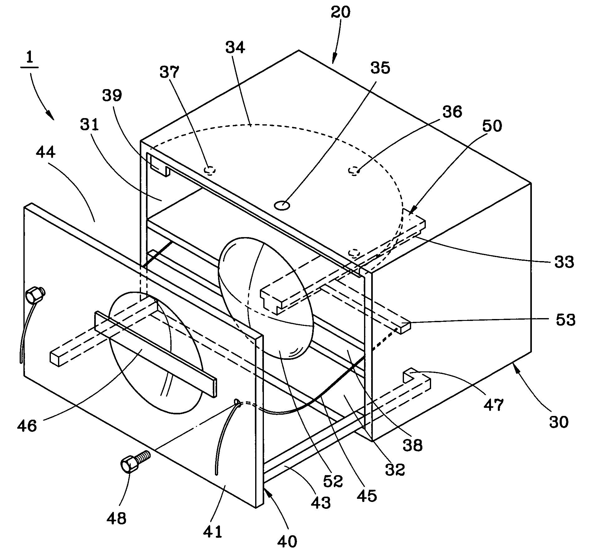
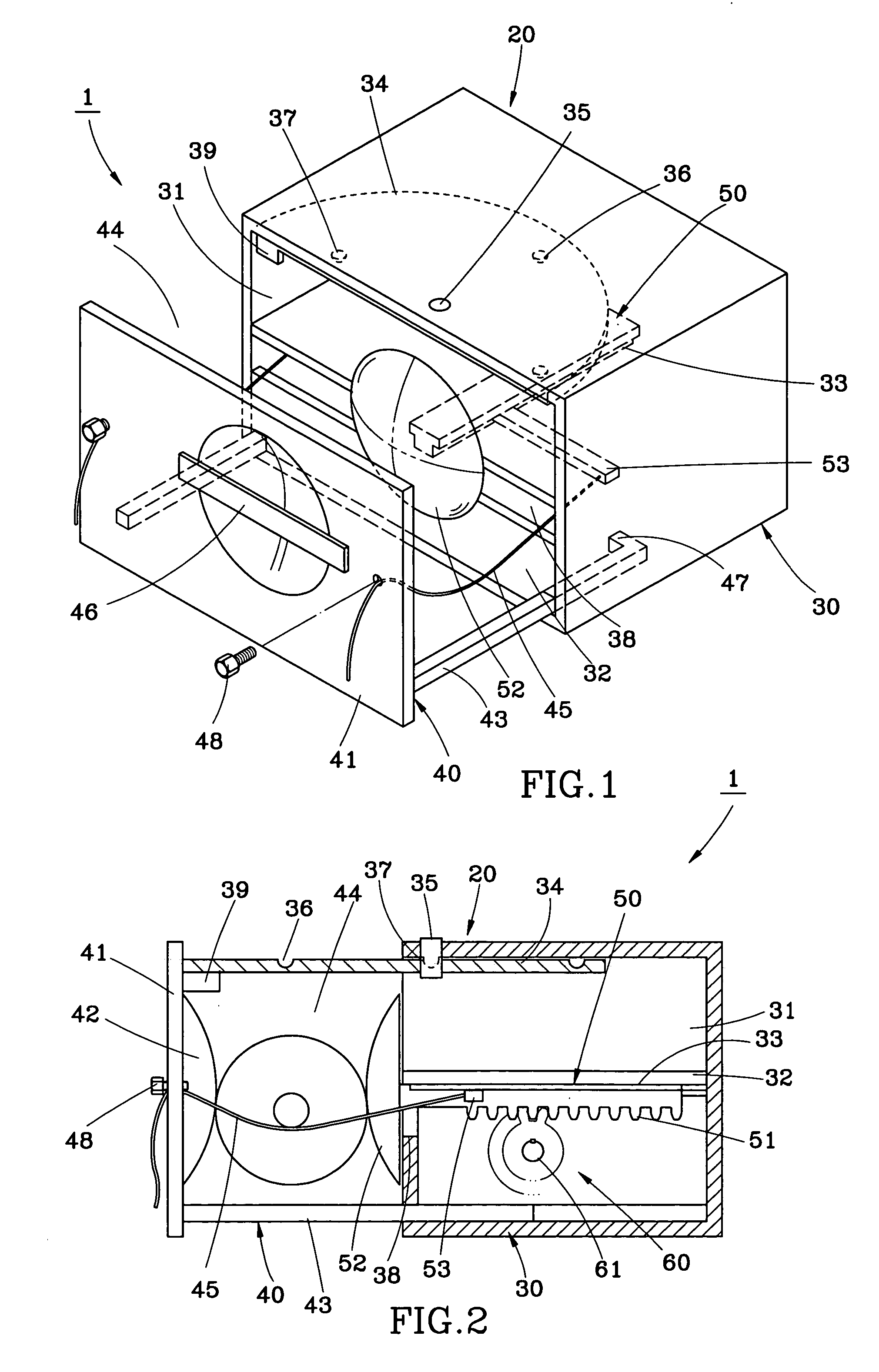
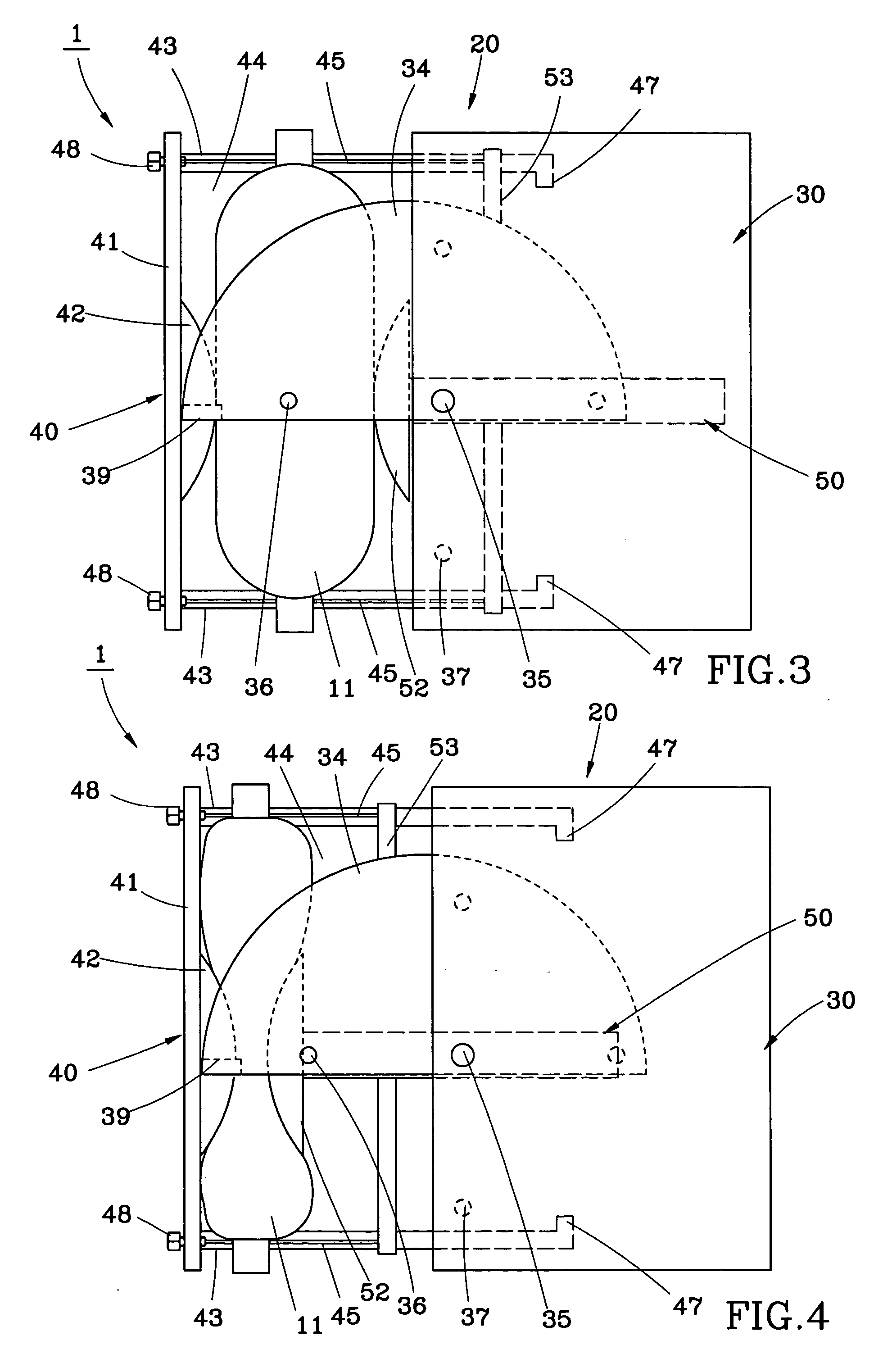
[0027]FIGS. 7 and 8 show an auto-pumping unit for use in a bag-valve-mask resuscitator according to a second preferred embodiment of the present invention. According to this design, the auto-pumping unit 70 is substantially similar to the aforesaid first embodiment, comprising a housing 71, a pressure device 75, and a driving mechanism 80. The housing 71 includes a hollow main body 72 and a movable part 73 movable relatively to the hollow main body 72. The hollow main body 72 and the movable part 73 define therebetween a receiving space 74. The pressure device 75 is mounted inside the main body 72 and movable relatively to the movable part 73. The driving mechanism 80 is provided for driving the pressure device 75 relatively to the movable part 73. In this embodiment, an elongated plate member 76 is mounted inside the hollow main body 72 at a top side of the housing 71 and movable in and out of the hollow main body 72. The elongated plate member 76 has an outer end extended out of t...

second embodiment

[0028] The aforesaid second embodiment uses a different design of driving mechanism and a different positioning arrangement between the movable part and the main body to achieve the same effect, fitting any of a variety of bags of different sizes to supply the air to the patient at a stable speed.

[0029]FIG. 9 shows an auto-pumping unit for use in a bag-valve-mask resuscitator according to a third embodiment of the present invention. Substantially similar to the aforesaid first and second preferred embodiments, the auto-pumping unit 90 of this third embodiment includes a housing 91, a pressure device 92, and a driving mechanism 100. The main features of this third embodiment are recited hereinafter. An elongated retractable member 95 is mounted between the main body 93 of the housing 91 and the movable part 94. The elongated retractable member 95 has an end connected to the bottom side of the movable part 94 and the other end inserted into the inside of the main body 93 and positione...


PUM


Abstract

An auto-pumping unit for a bag-valve-mask resuscitator includes a housing, a pressure device, and driving mechanism. The housing has a receiving space for accommodating a bag of the bag-valve-mask, and a baffle mounted at a side of the receiving space. The pressure device is movably mounted at the other side of the receiving space opposite to the baffle. The driving mechanism is mounted in the housing and controlled to drive the pressure device to move close to or away from the baffle to compress or release the bag at a predetermined speed.

Description

BACKGROUND OF THE INVENTION [0001] 1. Field of the Invention [0002] The present invention relates to generally to medical first-aid apparatuses, and more specifically to an auto-pumping unit for a bag-valve-mask resuscitator. [0003] 2. Description of the Related Art [0004] A conventional bag-valve-mask resuscitator (BVM) is a medical first-aid apparatus commonly used in an emergency case to help the patient breathe. When in use, the mask is covered on the patient's face over the mouse and the nose, and then the rubber ball is compressed at a predetermined frequency to supply the air to the patient to further regain or maintain the patient's life. [0005] During a process of first aid, the most important job to do is to keep the patient breathing. However, when the firs-aid personnel are rarely available on the spot, e.g. generally speaking, only one first-aid person is arranged in the ambulance, it is difficult to control various first-aid apparatuses and take care of the patient at ...

Claims


Application Information

Patent Timeline
IPC IPC(8): A61M16/00A62B9/06
CPCA61M16/0084A61M16/0057A61M2205/103A61M2205/106
Inventor LIN, JIMMY
Owner LIN JIMMY
Why Eureka
Try Eureka