
Method and apparatus for pulse-by-pulse calibration of a pulse-echo ranging system

Inactive Publication Date: 2005-12-22
SIEMENS MILLTRONICS PROCESS INSTRUMENTS
View PDF4 Cites 9 Cited by
  • Summary
  • Abstract
  • Description
  • Claims
  • Application Information

AI Technical Summary

Benefits of technology

[0010] In another aspect, the present invention provides a method for a level measurement instrument for determining a distance measurement to a target surface, the method comprises the steps of: emitting one or more pulses towards the target surface; receiving reflected pulses from said target surface, and determining a first measured parameter for at least one of said reflected pulses; receiving one or more pulses reflected by a reference surface, and determining a second measured parameter for at least one of said reflected reference pulses; forming a ratio between said first measured parameter for said reflected pulses and said second measured parameter for said reflected reference pulses; determining a distance measurement to said reference surface; determining the distance measurement to the target surface based on said ratio and said distance measurement to said reference surface.
[0011] In a further aspect, the present invention provides an apparatus for performing level measurements of a material contained a vessel and having a surface, the apparatus comprises: a transducer for emitting pulses towards to the surface of the material contained in the vessel and detecting echo pulses reflected by the surface of the material; a transmitter coupled to the transducer, the transmitter being responsive to transmit control signals for controlling emission of pulses from the transducer; a receiver coupled to the transducer, the receiver converting the reflected pulses received by the transducer into electrical signals corresponding to the received reflected pulses; a controller, the controller being operatively coupled to the transmitter and having a program component for generating the transmit control signals, and the controller being operatively coupled to the receive

Problems solved by technology

Since the transmitted energy pulses are converted into distance measurements, any timing errors arising in the circuitry of the device result in distance measurement errors which degrade the accuracy of the level measurements.
In most cases, errors arise due to temperature changes or temperature effects.
Timing errors are a result of temperature drift and drift over time in the operating characteristics of the electronics in the device circuitry.
Temperature changes also give rise to speed errors in the transmission and reception of the energy pulses.

Method used


Image

  • Method and apparatus for pulse-by-pulse calibration of a pulse-echo ranging system
  • Method and apparatus for pulse-by-pulse calibration of a pulse-echo ranging system
  • Method and apparatus for pulse-by-pulse calibration of a pulse-echo ranging system

Examples


Embodiment Construction

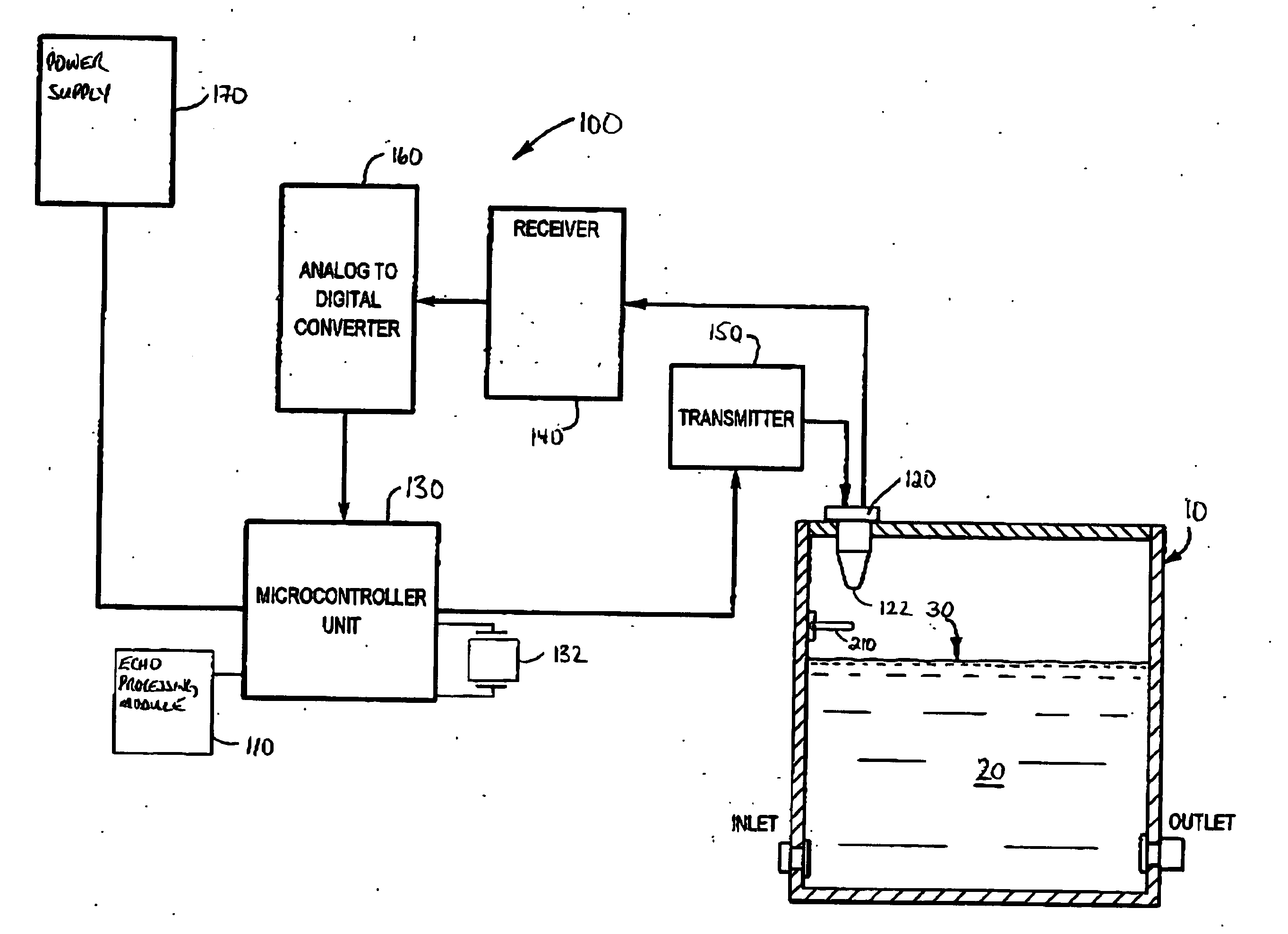
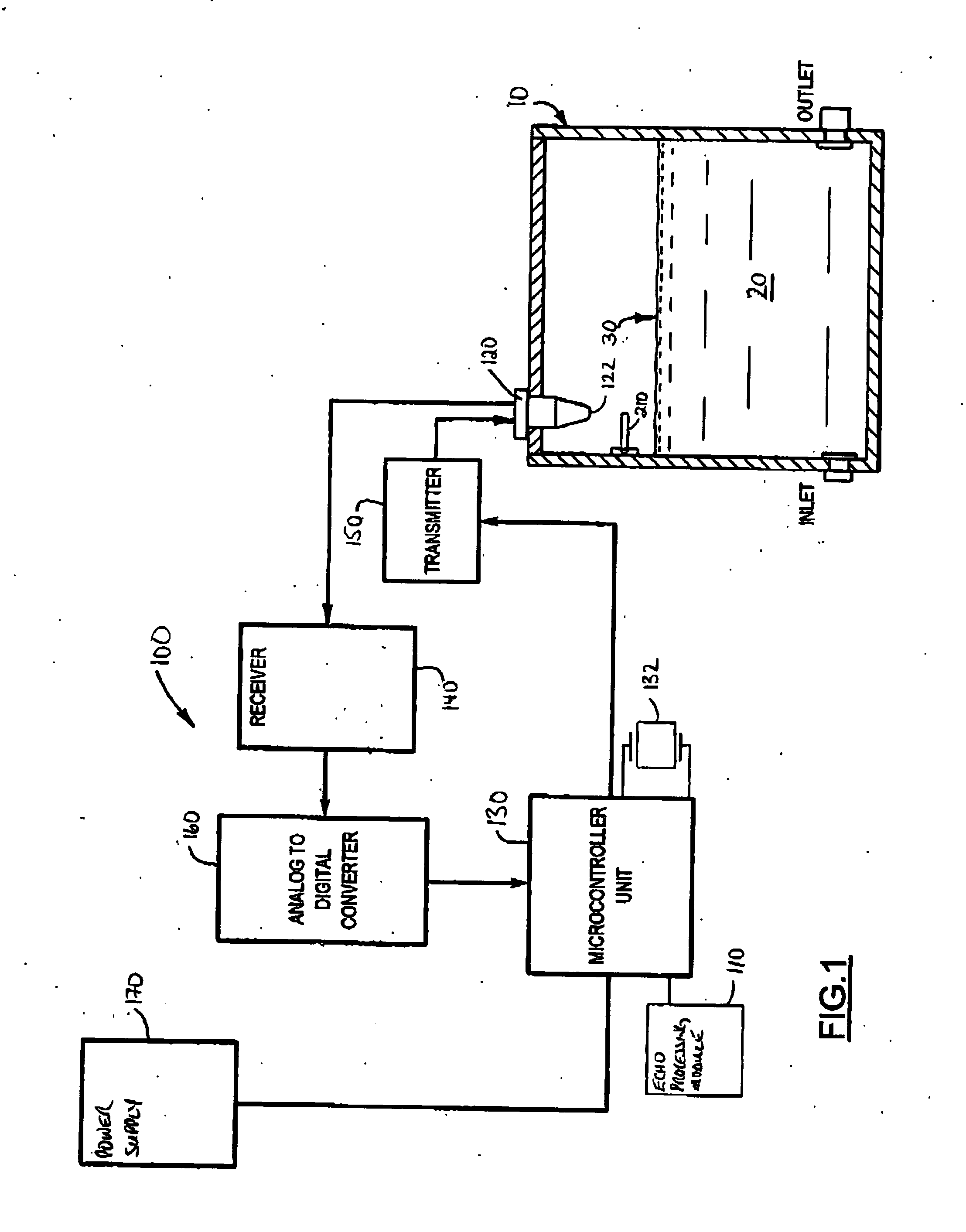
[0019] Reference is first made to FIG. 1, which shows a pulse-echo level measurement system 100 in accordance with the present invention.

[0020] As shown in FIG. 1, the pulse-echo level measurement system 100 is installed in a vessel 10, e.g. a storage tank, containing a material 20, for example, a liquid, sludge or granular material, having a level determined by the top surface of the material 20. The top surface of the material 20 provides a reflective surface or reflector, indicated by reference 30, which reflects pulses (e.g. ultrasonic pulses or radar energy bursts emitted by a transducer).

[0021] The pulse-echo level measurement system 100 includes an echo processing module 110, a transducer 120, a controller or signal processor unit 130, a receiver module 140, a transmitter module 150, an analog-to-digital (A / D) converter 160 and a power supply unit 170. In other implementations, the power supply 170 may be replaced by a loop powered interface (not shown). The controller 130,...


PUM


Abstract

A level measurement or time of flight ranging apparatus for determining a distance measurement to the surface of a material. The apparatus comprises a transducer, a transmitter, a receiver and a processor. In response to the transmitter, the transducer emits energy pulses towards the surface of the material. The transducer detects pulses reflected by the material surface and the receiver converts the reflected pulses into signals for further processing by the processor. The apparatus further includes a mechanism for reflecting a reference pulse from a known distance with respect to the transducer. The processor determines a ratio between the reference distance (or reference pulse time of travel) and the reflected pulse(s) (or reflected pulse time of travel). The ratio is used with the reference distance to determine the distance measurement to the surface of the material.

Description

FIELD OF THE INVENTION [0001] The present invention relates to time-of-flight ranging or pulse-echo ranging systems and, in particular, to a method and apparatus for calibrating and improving the accuracy of pulse-echo ranging systems. BACKGROUND OF THE INVENTION [0002] Pulse-echo acoustic ranging systems, also known as time-of-flight ranging systems, are commonly used in level measurement applications. Pulse-echo acoustic ranging systems determine the distance to a target or reflector (i.e. reflective surface) by measuring how long after transmission of a burst of energy pulses the echo or reflected pulses are received. Such systems typically use ultrasonic pulses or pulse radar signals. [0003] Pulse-echo acoustic ranging systems generally include a transducer and a signal processor. The transducer serves the dual role of transmitting and receiving the energy pulses. The signal processor is for detecting and calculating the distance or range of the object based on the transmit time...

Claims


Application Information

Patent Timeline
IPC IPC(8): G01F23/284G01F23/296G01S7/52G01S15/88
CPCG01F23/284G01F23/2962G01S7/52004G01S2007/4082G01S7/40G01S7/4052G01S15/88G01S7/4082
Inventor FERREIRA, EDSON LEOCADIO
Owner SIEMENS MILLTRONICS PROCESS INSTRUMENTS
Learn More