
Helicopter tail section and retrofit method

a tail section and helicopter technology, applied in the field of helicopters, can solve the problems of affecting the function and efficiency of the helicopter, the blockage effect of the conventional vertical stabilizer, etc., and achieve the effects of reducing the power requirements of the tail rotor, improving the flying qualities of the helicopter, and reducing the working of the tail section of the helicopter

Active Publication Date: 2005-12-22
BLR AEROSPACE
View PDF3 Cites 2 Cited by
  • Summary
  • Abstract
  • Description
  • Claims
  • Application Information

AI Technical Summary

Benefits of technology

[0009] An object of the present invention is to improve the flying qualities of the helicopter. The working of the tail section of the helicopter is reduced, solving or lessening fatigue problems. The power requirements of the tail rotor are reduced, resulting in more power being available for operation of the main rotor.

Problems solved by technology

The blockage effect of a conventional vertical stabilizer is detrimental to the function and efficiency of the helicopter.

Method used


Image

  • Helicopter tail section and retrofit method
  • Helicopter tail section and retrofit method
  • Helicopter tail section and retrofit method

Examples


Embodiment Construction

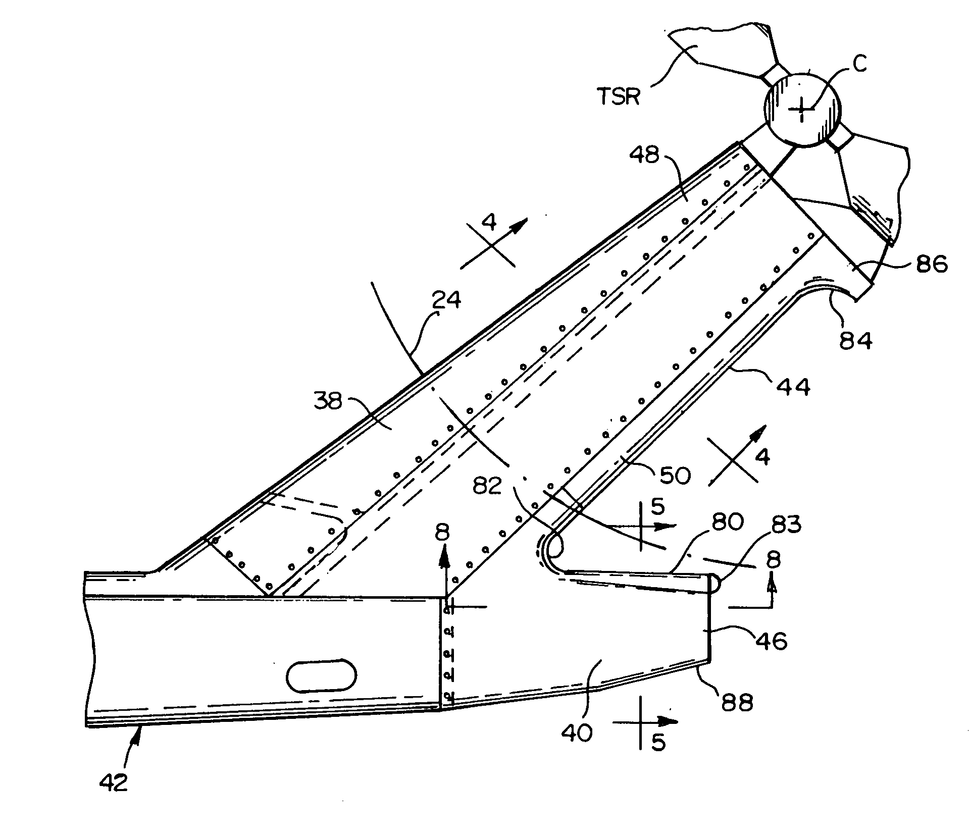
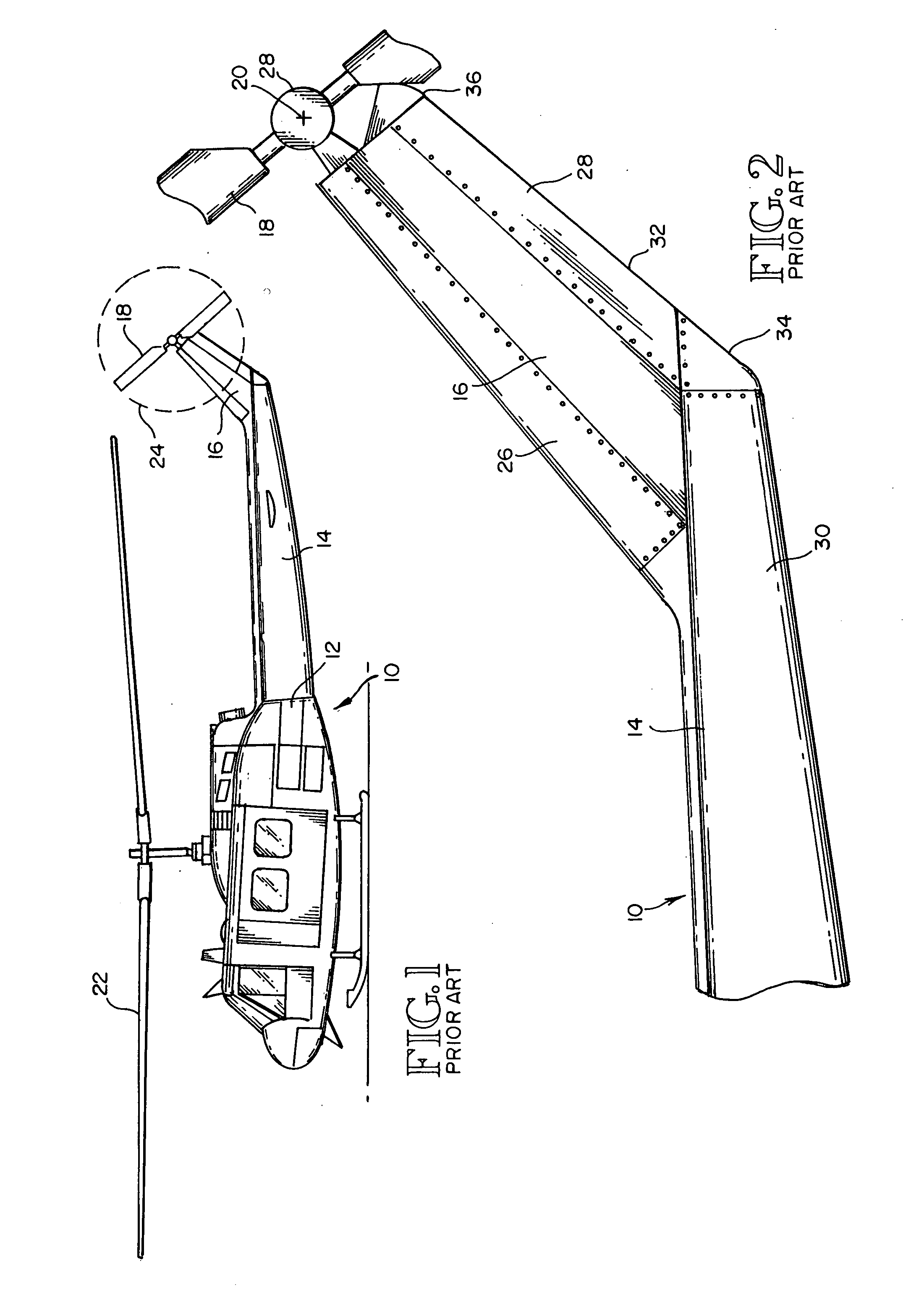
[0020]FIGS. 1 and 2 show a prior art helicopter 10, characterized by a fuselage 12 having a tail section 14 and a vertical stabilizer 16 mounted on and extending upwardly and rearwardly from the tail section 14. A tail rotor 18 is mounted for rotation about a horizontal axis 20 at or above the upper end of the rear stabilizer 16. A main rotor 22 is mounted on the fuselage 12 near the front of the helicopter. This helicopter is generally like the helicopter disclosed by the aforementioned U.S. Design Pat. No. D278,227.

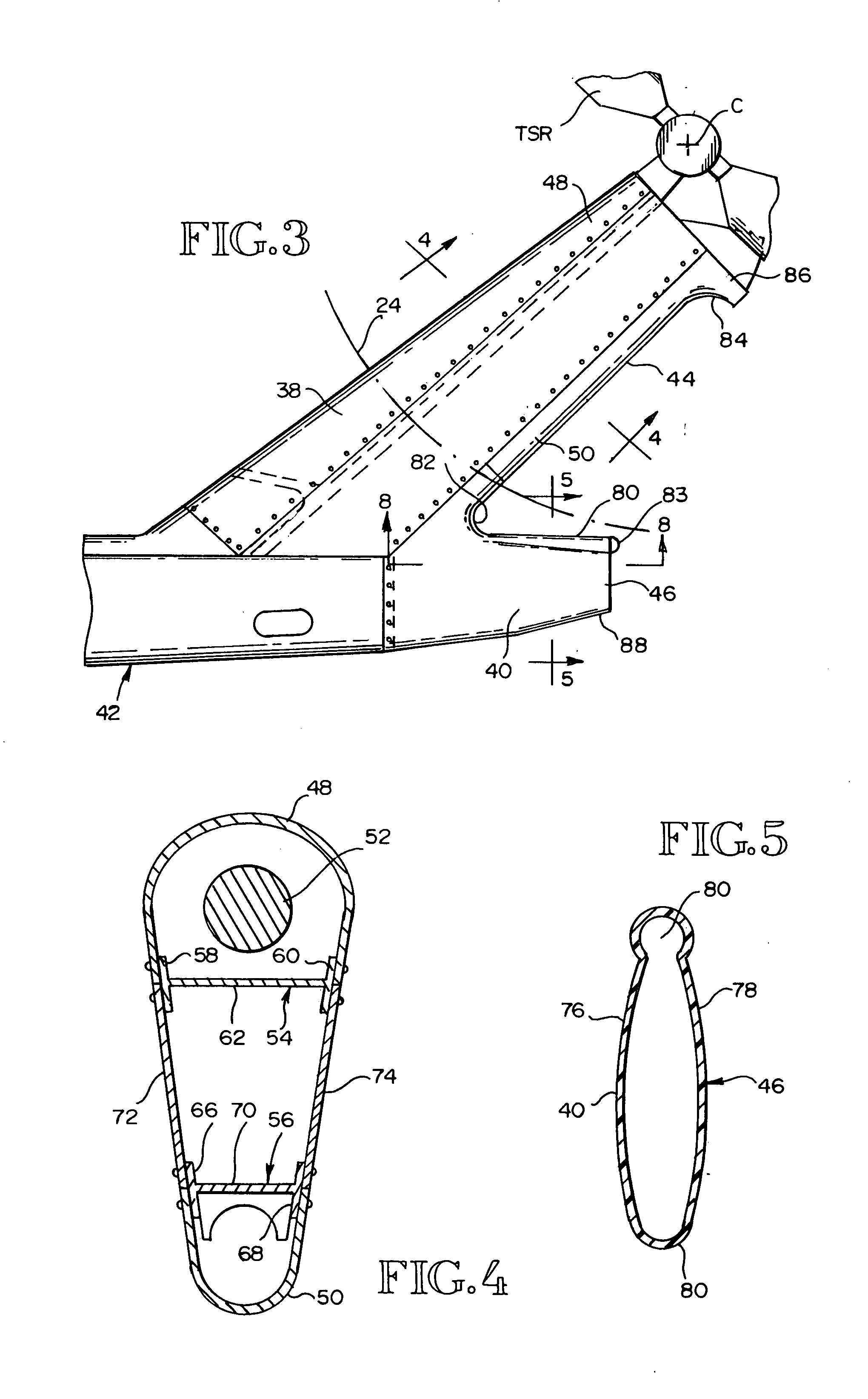
[0021] In FIG. 1, the fly diameter of the tail rotor 18 is designated 24. It defines the outline of a sideways airstream that is created by the tail rotor 18. The side location and direction of rotation of the tail section rotor TSR is a variable. It can be placed on either the left or the right side of the tail section 38. Also, it may rotate forwardly or rearwardly. It may push the airstream into the vertical stabilizer 38 or pull it into the vertical stabilizer 38. ...


PUM


Abstract

A vertical stabilizer (38) is supported by and projects upwardly and rearwardly from the tail portion (14) of a helicopter fuselage (12). A tail rotor (TSR) is mounted on the vertical stabilizer (38) for rotation about a horizontal axis (C). The tail rotor (TSR) is positioned laterally outwardly from one side of the vertical stabilizer (38). The vertical stabilizer (38) has an upper end, a lower end and a rear edge recess (44) located between the upper end and the lower end. The recess (44) has a laterally convex rear edge (50). The tail portion (14) of fuselage (12) has a rear end extension (40) that extends rearwardly from the vertical stabilizer (38) and narrows in width as it extends rearwardly. The rear end extension (40) of the fuselage (12) provides vertical area to replace vertical area that was removed by placement of the recess (44) in the vertical stabilizer (38). A corner (82) is formed where the rear edge of the vertical stabilizer (50) meets the upper edge (80) of the rear end extension (40) of the fuselage (12). The corner (82) is laterally convex and vertically concave. The upper end of the vertical stabilizer (38) is wider than the vertical stabilizer is in the region of the rear edge recess (44). The upper end of the vertical stabilizer (38) forms a corner (84) with the rear edge recess (44). This corner (84) is laterally convex and vertically concave. The rear end extension (40) of the tail portion (14) of the fuselage (12) has a forward portion including sides that are convex in the vertical direction and a rear end portion that is substantially straight in the vertical direction. The rear end extension (40) of the tail section (14) of the fuselage (12) is both laterally and longitudinally convex.

Description

TECHNICAL FIELD [0001] This invention relates to a helicopter having a tail portion, a vertical stabilizer supported by and projecting upwardly and rearwardly from the tail portion, and a tail rotor mounted on one side of the vertical stabilizer for rotation about a horizontal axis. More particularly, it relates to a construction of the tail portion and the vertical stabilizer that reduces aerodynamic load and stress and wear on the tail portion of the helicopter. It also relates to a retrofit method. BACKGROUND OF THE INVENTION [0002] In single rotor helicopters, a lifting force and a propulsive force are provided by a main lifting rotor and yaw control is provided by a second, smaller rotor mounted on a vertical stabilizer at the rear or fail of the fuselage. This second rotor, herein the “tail rotor”, is positioned laterally outwardly from one side of the vertical stabilizer and is mounted at the upper end of the vertical stabilizer for rotation about a horizontal axis. Rotation ...

Claims


Application Information

Patent Timeline
Patent Type & Authority Applications(United States)
IPC IPC(8): B64C27/82
CPCB64C27/82
Inventor DESROCHE, ROBERT J.
Owner BLR AEROSPACE
Learn More