
Driving force control apparatus for automotive vehicles

a technology for driving force control and automobiles, which is applied in the direction of machines/engines, instruments, transportation and packaging, etc., can solve the problems of deteriorating the convergence performance of acceleration-slip suppression control for the main drive wheel side, rapid reduction or release of generator's load on the engine, etc., and achieves the effect of suppressing acceleration slip

Inactive Publication Date: 2005-12-15
NISSAN MOTOR CO LTD
View PDF2 Cites 24 Cited by
  • Summary
  • Abstract
  • Description
  • Claims
  • Application Information

AI Technical Summary

Benefits of technology

[0004] Accordingly, it is an object of the invention to provide a vehicle driving force control apparatus capable of effectively suppressing acceleration slip of a subsidiary drive wheel side without deteriorating a convergence performance of acceleration-slip suppression for a main drive wheel side.
[0006] According to another aspect of the invention, a driving force control apparatus for an automotive vehicle employing an engine that drives a main drive wheel, a generator driven by the engine, and a motor driven by an electric power output generated by the generator to drive a subsidiary drive wheel, comprises a subsidiary-drive-wheel acceleration slip estimation circuitry that estimates an acceleration slip rate of the subsidiary drive wheel, an electric power output suppression circuitry that suppresses the electric power output of the generator by a reduced value when the estimated subsidiary-drive-wheel acceleration slip rate exceeds a predetermined slip rate, and a target engine output torque reduction circuitry that reduces a target engine output torque by a load torque value corresponding to the reduced value of the electric power output responsively to suppressing the electric power output.
[0011] According to another aspect of the invention, a method of controlling driving forces applied to a main drive wheel and a subsidiary drive wheel of an automotive vehicle employing an engine that drives the main drive wheel, a generator driven by the engine, a motor driven by an electric power output generated by the generator to drive the subsidiary drive wheel, and sensors that detect slip velocities of the main drive wheel and the subsidiary drive wheel and a driver-required vehicle acceleration, the method comprises estimating, based on the slip velocity of the main drive wheel, a main-drive-wheel acceleration slip rate, estimating, based on the slip velocity of the subsidiary drive wheel, a subsidiary-drive-wheel acceleration slip rate, calculating a first target motor torque based on the slip velocity of the main drive wheel, calculating a second target motor torque based on the driver-required vehicle acceleration, selecting a higher one of the first and second target motor torques as a target motor torque, reducing the target motor torque by a reduced torque value determined based on the estimated subsidiary-drive-wheel acceleration slip rate when the estimated subsidiary-drive-wheel acceleration slip rate exceeds a predetermined slip rate, suppressing the electric power output of the generator by a reduced value corresponding to the reduced torque value when the estimated subsidiary-drive-wheel acceleration slip rate exceeds the predetermined slip rate, and reducing an engine output torque responsively to suppressing the electric power output.

Problems solved by technology

On the other hand, suppressing the generator's electric power output means that the generator's load carried on the engine is rapidly reduced or released, thus deteriorating the convergence performance of acceleration-slip suppression control for the main drive wheel side.

Method used


Image

  • Driving force control apparatus for automotive vehicles
  • Driving force control apparatus for automotive vehicles
  • Driving force control apparatus for automotive vehicles

Examples


Embodiment Construction

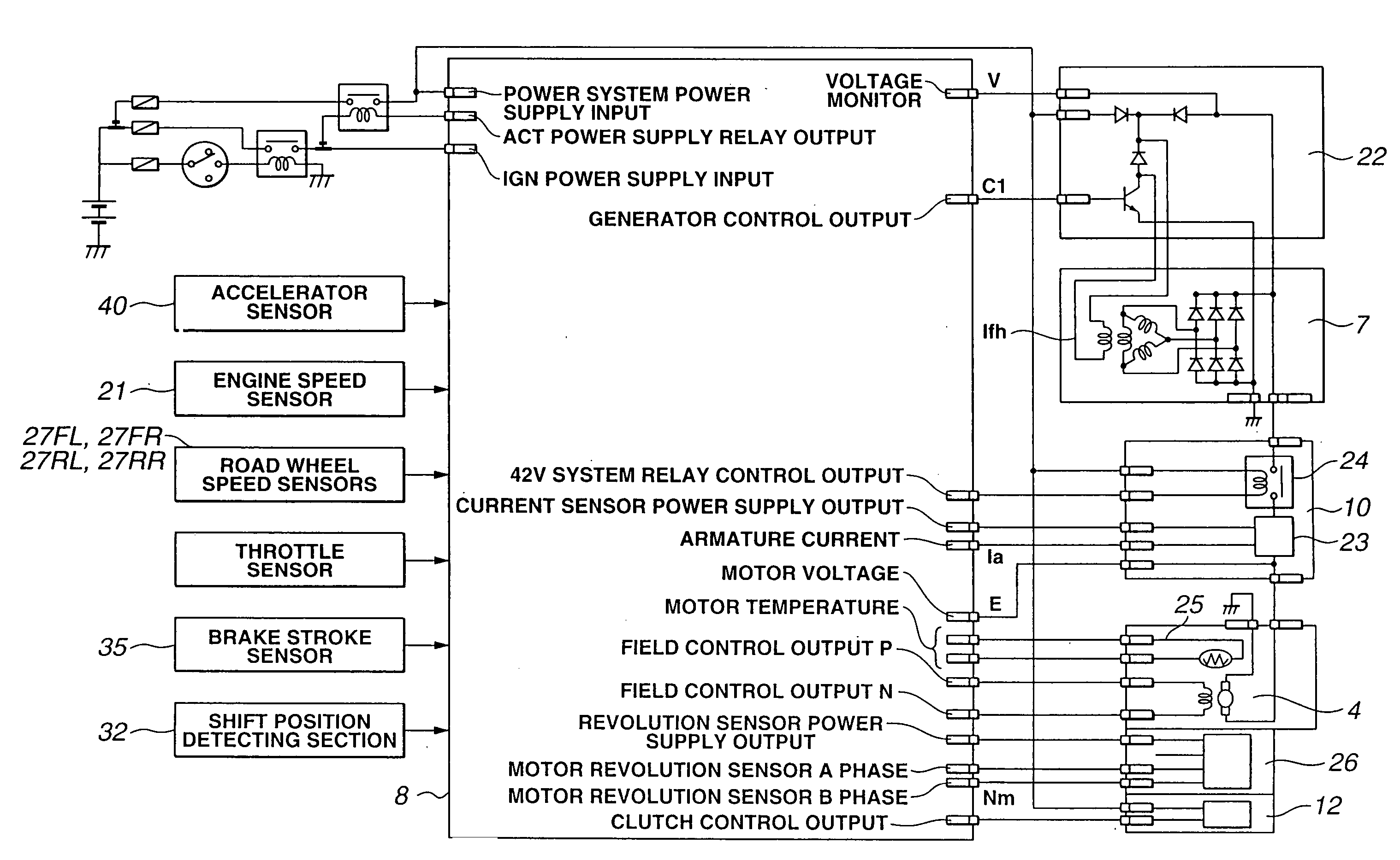
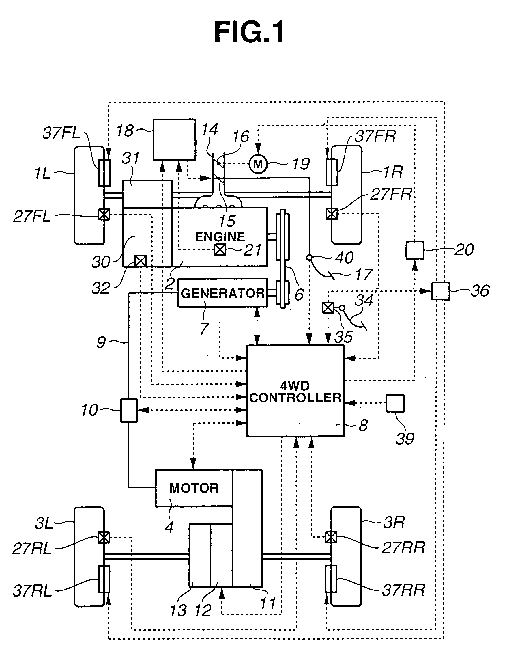
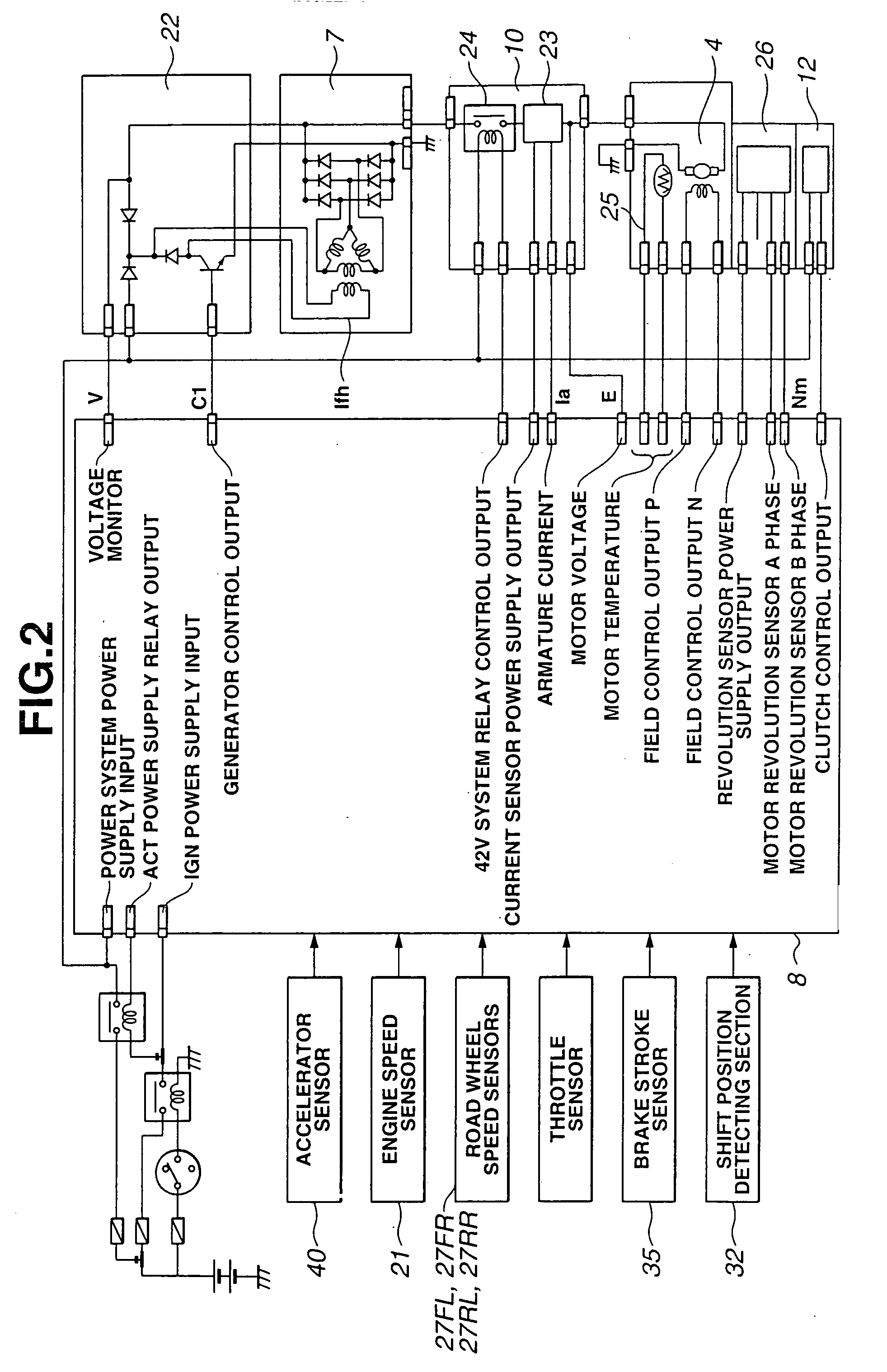
[0025] Referring now to the drawings, particularly to FIG. 1, the vehicle driving force control apparatus of the embodiment is exemplified in a four-wheel-drive (4WD) vehicle in which front-left and front-right road wheels 1L and 1R are main drive wheels driven by an engine 2, and rear-left and rear-right road wheels 3L and 3R are subsidiary drive wheels driven by a motor 4. An output torque Te produced by engine 2 is transmitted through a transmission 30 and a front differential gear 31 to front-left and front-right road wheels 1L and 1R.

[0026] A shift position detector (or a shift position detecting device) 32 is provided in or attached to transmission 30 for detecting a selected operating range of the transmission and for generating a shift position signal indicative of the selected operating range to a 4WD controller 8. The automatic shift sequence of transmission 30 is performed responsively to an automatic shift command from an electronic transmission controller (not shown). ...


PUM


Abstract

In a driving force control apparatus for an automotive vehicle employing an engine that drives a main drive wheel, a generator driven by the engine, and a motor driven by an electric power output generated by the generator to drive a subsidiary drive wheel, a subsidiary-drive-wheel acceleration slip estimation circuitry is provided to estimate a subsidiary-drive-wheel acceleration slip rate. An electric power output suppression circuitry is provided to suppress the electric power output of the generator when the estimated subsidiary-drive-wheel acceleration slip rate exceeds a predetermined slip rate. Also provided is a subsidiary-drive-wheel acceleration-slip period engine output torque reduction circuitry that reduces an engine output torque responsively to suppressing the electric power output.

Description

TECHNICAL FIELD [0001] The present invention relates to a driving force control apparatus for automotive vehicles, and specifically to a vehicle driving force control apparatus capable of driving a generator by an internal combustion engine that drives main drive wheels and supplying electric power generated by the generator to a motor that drives subsidiary drive wheels. BACKGROUND ART [0002] In recent years, there have been proposed and developed various vehicle driving force control apparatus in which main drive wheels (either front or rear road wheels) are driven by an engine and subsidiary drive wheels (the remaining road wheels) are driven by a motor. One such vehicle driving force control apparatus has been disclosed in Japanese Patent Provisional Publication No. 7-231508 (hereinafter is referred to as “JP7-231508”). In the vehicle driving force control apparatus disclosed in JP7-231508, a generator is driven by an engine, whereas a motor is driven by electric energy generate...

Claims


Application Information

Patent Timeline
IPC IPC(8): B60K6/20B60W20/00B60K6/44B60K6/52B60K17/356B60L15/20B60L50/13B60L50/16B60W10/06B60W10/08F02D29/02F02D29/06
CPCB60K6/44B60K6/52B60W10/06B60W10/08Y02T10/7258B60W2520/26Y02T10/623Y02T10/6265Y02T10/6286B60W20/00Y02T10/62Y02T10/72B60W20/15
Inventor MASUDA, REISHIMIZU, KOUICHI
Owner NISSAN MOTOR CO LTD
Learn More