
Communication network event logging systems and methods

Inactive Publication Date: 2005-12-15
ALCATEL LUCENT SAS
View PDF6 Cites 121 Cited by
  • Summary
  • Abstract
  • Description
  • Claims
  • Application Information

AI Technical Summary

Benefits of technology

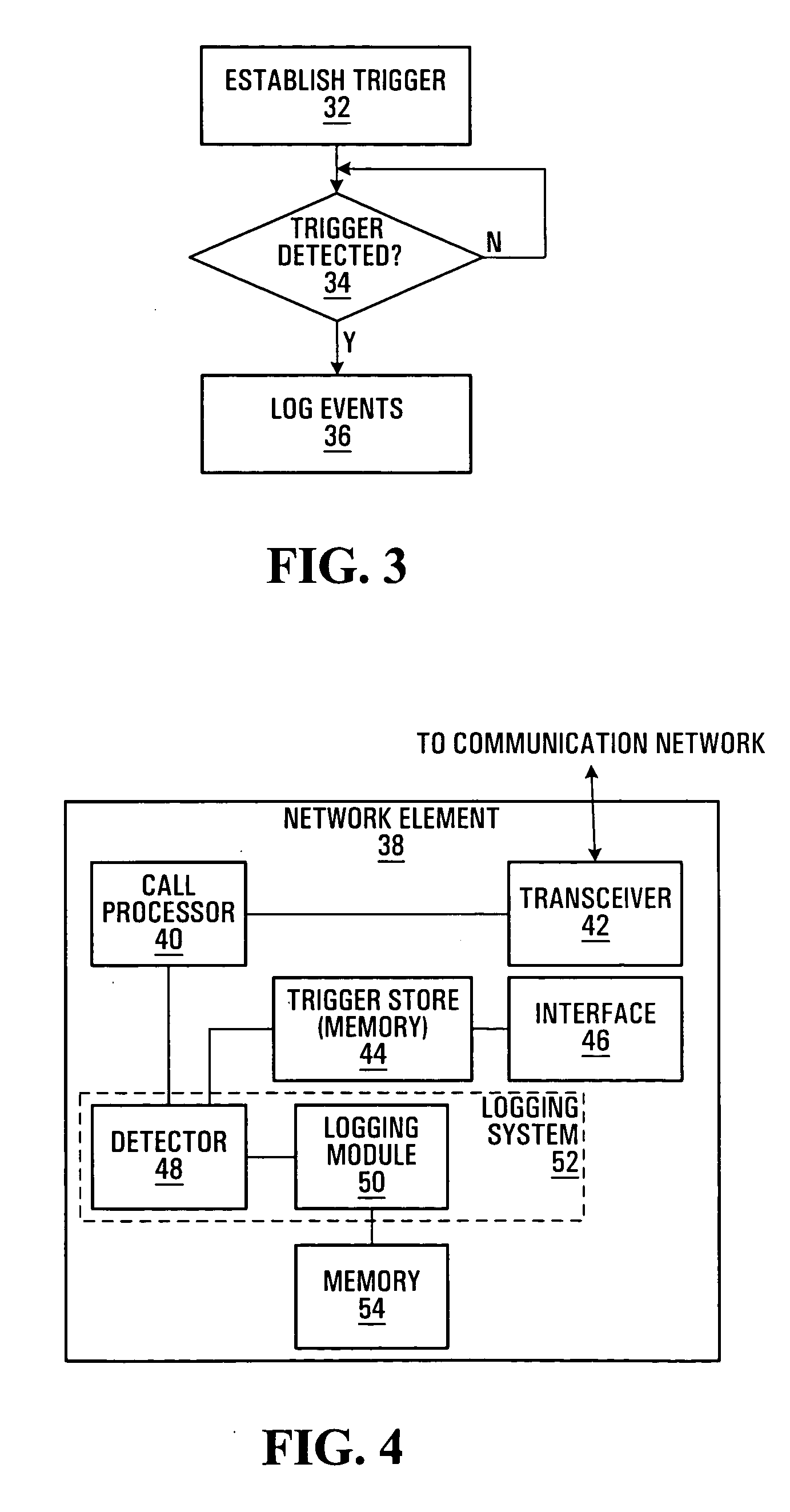
[0010] Improved logging methods and systems for communication networks are provided. Events, illustratively protocol traces, associated with particular calls or other types of communication session are logged on a per-session basis, for only those sessions for which an event logging trigger has been detected. Per-session logging may thus drastically reduce the number of logs, thereby alleviating some of the problems described above. An operator can then more easily scan logs at different network elements in a communication network to quickly diagnose a problem.

Problems solved by technology

Diagnosing failures or problems in communication networks, such as failed telephone or data call attempts, for example, can be particularly challenging in busy networks with a relatively high level of setup or control plane traffic.
In the presence of a high volume of setup traffic or other signalling messages used to establish, maintain, or end a call, it becomes difficult to retrieve a signalling message history, also generally referred to as a protocol trace, for specific calls which fail.
This difficulty arises primarily from the typically large volume of similar protocol traces for other calls in progress in a communication network at the same time.
However, the signalling trace function may result in very large volumes of protocol traces being collected on a node or nodes where suspect calls are failing.
In addition, protocol traces may be collected for several minutes or even longer before a failure or problem is repeated.
As described above, this task can be intensive and time consuming due to the number of traces collected.
Trace searching is further complicated by the similarity between protocol traces.
There is also a possibility that trace logs at a node do not contain the required traces.
This situation may occur, for example, where required traces have overwritten due to limited protocol trace log storage space or where the path of a call through the network is unknown and the operator is accessing trace logs at a node through which a call being traced was not established.
Thus, the time spent searching must be weighed against the possibility that the search will be unsuccessful.
This uncertainty further increases the difficulty of diagnosing communication network problems using conventional logging techniques.
However, the transfer itself is a time consuming process, which consumes both CPU resources at each node and network resources throughout the network, and does not reduce the large volume of logged traces requiring inspection.
Since each interface typically supports a large number of connections, interface-specific trace logs are also often very large, and thus extraction of any information of interest for particular calls remains difficult.
However, this technique has a very limited logging trigger capability, such as a calling address, involves proprietary signalling trace formats, and does not provide for trigger detection and event logging at multiple nodes through which a call is routed.

Method used


Image

  • Communication network event logging systems and methods
  • Communication network event logging systems and methods
  • Communication network event logging systems and methods

Examples


Embodiment Construction

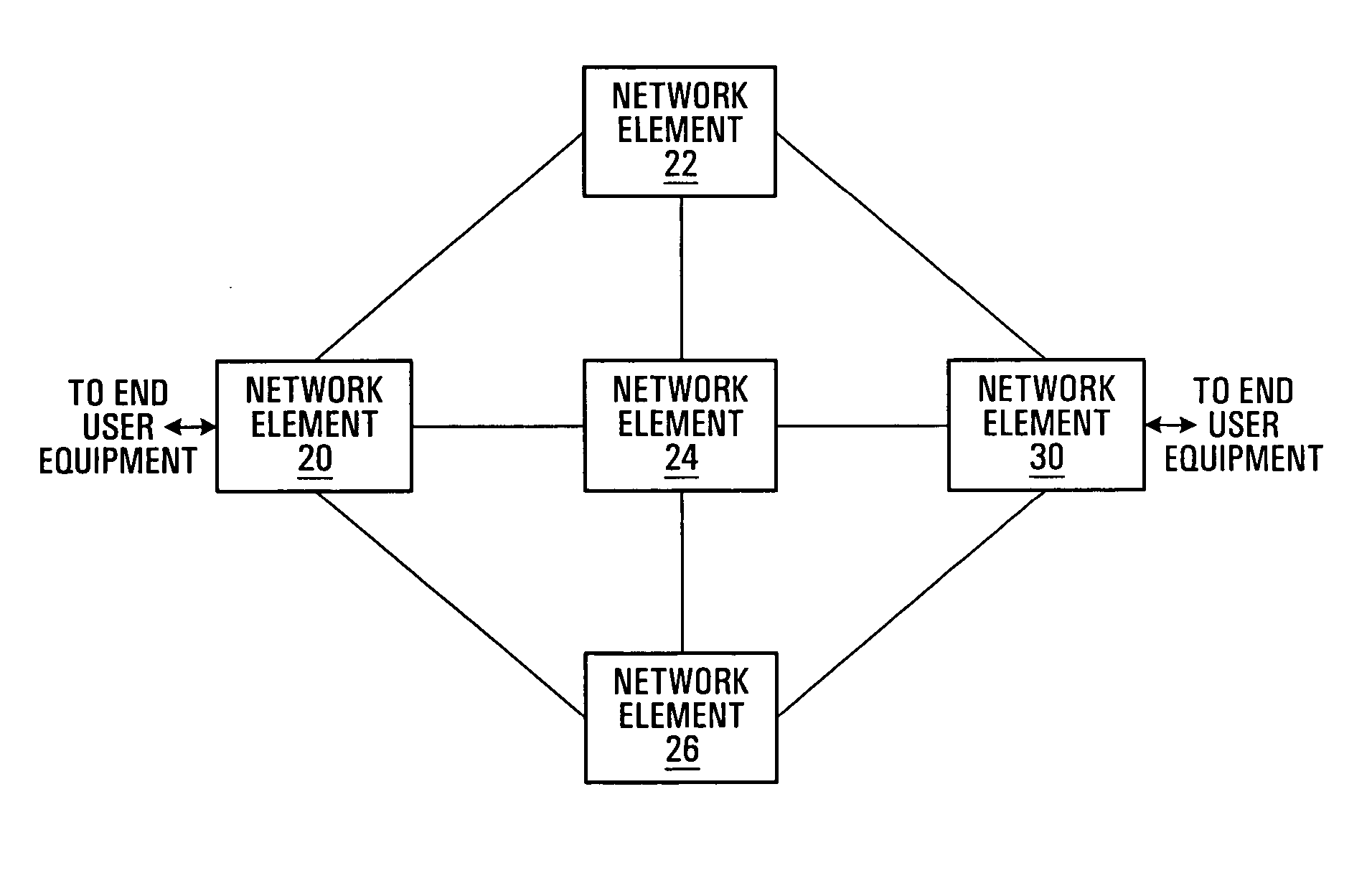
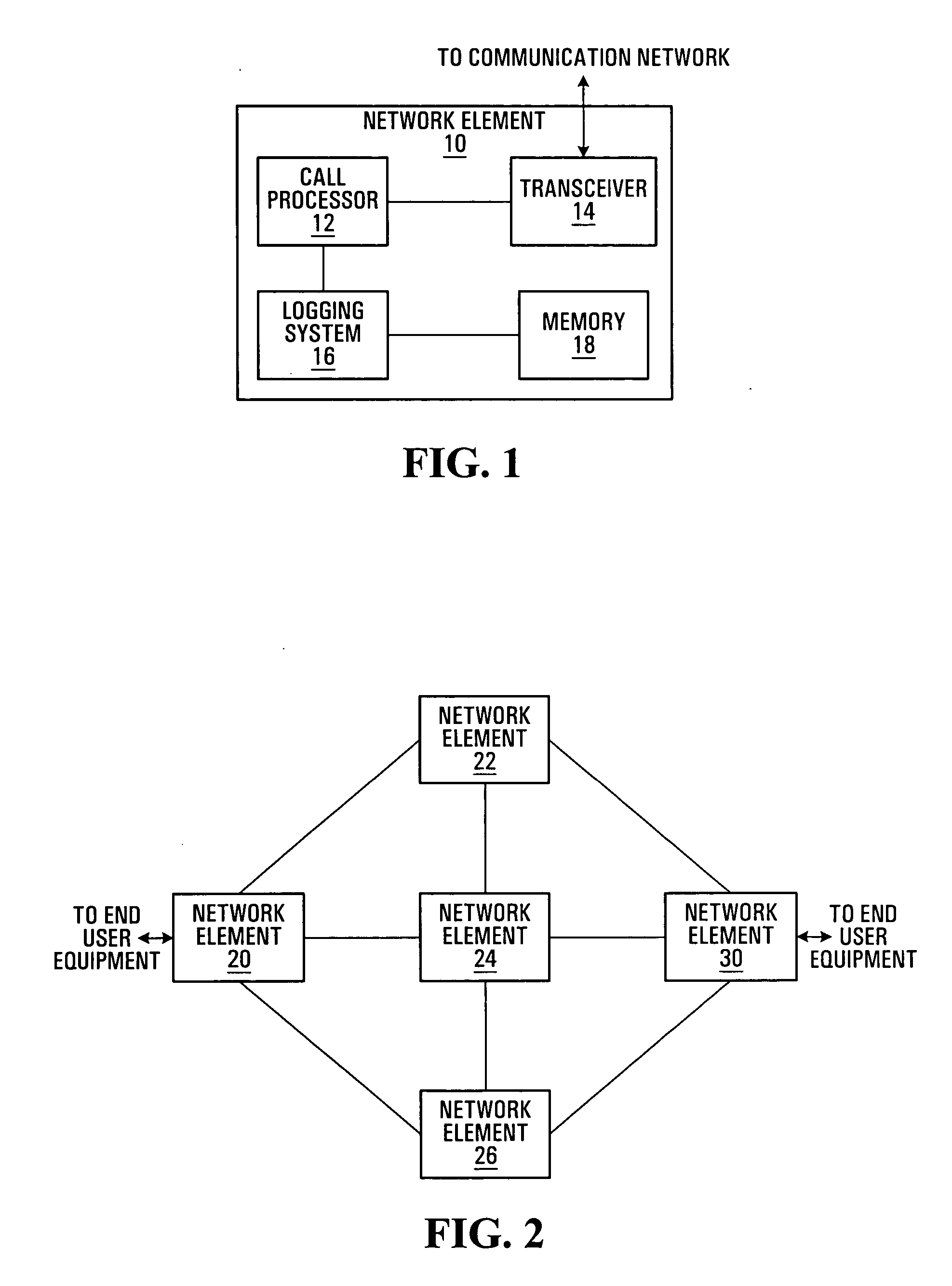
[0033]FIG. 2 is a block diagram of a communication network in which embodiments of the invention may be implemented. The communication network in FIG. 2 includes multiple network elements 20, 22, 24, 26, 30, also commonly referred to as nodes. As embodiments of the present invention are preferably implemented at network elements within a communication network, other equipment which may be provided within a communication network or operate in conjunction with a communication network, such as end user equipment, network management systems, and other user, management, or control equipment, has not been explicitly shown in FIG. 2. It should therefore be appreciated that the system of FIG. 2, as well as the contents of the other drawings, is intended solely for illustrative purposes. Embodiments of the present invention are in no way limited to any particular type of network, equipment, or communications.

[0034] The network elements 20, 22, 24, 26, 30 may be switches, routers, or analogo...


PUM


Abstract

Event logging methods and systems for communication networks are provided. Events associated with particular communication sessions are logged responsive to detection of any of a plurality of event logging triggers which have been established for the communication sessions. Per-session event logging according to embodiments of the invention may provide improved event logging functions for communication network fault or error analysis by enabling enhanced trigger-based event logging control and logging of a wide range of events, including standards-based signalling messages, at network elements throughout a communication network.

Description

FIELD OF THE INVENTION [0001] This invention relates generally to communication networks and, in particular, to logging events associated with communication networks. BACKGROUND [0002] Diagnosing failures or problems in communication networks, such as failed telephone or data call attempts, for example, can be particularly challenging in busy networks with a relatively high level of setup or control plane traffic. In the presence of a high volume of setup traffic or other signalling messages used to establish, maintain, or end a call, it becomes difficult to retrieve a signalling message history, also generally referred to as a protocol trace, for specific calls which fail. This difficulty arises primarily from the typically large volume of similar protocol traces for other calls in progress in a communication network at the same time. [0003] According to one conventional technique, a failed call attempt is diagnosed by running a trace on signalling messages used in the setup of the...

Claims


Application Information

Patent Timeline
IPC IPC(8): H04L12/24H04L12/26
CPCH04L12/2602H04L43/16H04L43/00H04L41/069
Inventor MCCORMICK, JAMES STEWARTWELLS, DONBADIAL, KULPREET SINGH
Owner ALCATEL LUCENT SAS
Learn More