
Biofeedback ring sensors

a technology of biofeedback and ring sensor, which is applied in the field of biofeedback sensors, can solve the problems of unsatisfactory removal experience, frequent replacement of attachment devices, and wear and tear of attachment devices, and achieves the effects of not being well suited for all individuals, and being frequently bulky

Inactive Publication Date: 2005-12-08
HEALING RHYTHMS
View PDF3 Cites 58 Cited by
  • Summary
  • Abstract
  • Description
  • Claims
  • Application Information

AI Technical Summary

Benefits of technology

"The present invention provides an improved finger sensor that can measure biometric information when a client's appendage is in a resting state. The sensor is connected to a cover or wing that is attached to a biasing member that provides a compressive force to the appendage. This ensures that the appendage is snuggly contained in the resting state. Additionally, the invention provides a system for obtaining multiple biometric information using multiple sensors, each with a cover pivotally connected to the appendage rest. This allows for the simultaneous measurement of biometric information from multiple sensors."

Problems solved by technology

The electrode sensors are good measures of electrical information, such as epidural skin response, which is a measure of skin resistance and useful for measuring stress or the like, the use of adhesives on the client can result in an unpleasant removal experience.
Frequently, the attachment devices wear out requiring frequent replacement.
While these clips work somewhat better than the attachment devices above, they are frequently bulky and not well suited for all individuals.

Method used


Image

  • Biofeedback ring sensors
  • Biofeedback ring sensors
  • Biofeedback ring sensors

Examples


Embodiment Construction

[0019] The present invention will be explained with specific reference to FIGS. 1 to 8. It is to be understood that the drawings are diagrammatic and schematic representations of particular embodiments of the present invention, and are not limiting, nor are they drawn to scale. Further, while the present invention is described in relation to a finger sensor, the sensor could be placed in other locations, such as a toe or the like. Finally, while the present invention is described using an electrode and / or an infrared biofeedback sensor, one of ordinary skill in the art would recognize on reading the disclosure that other types of biofeedback sensors could be used.

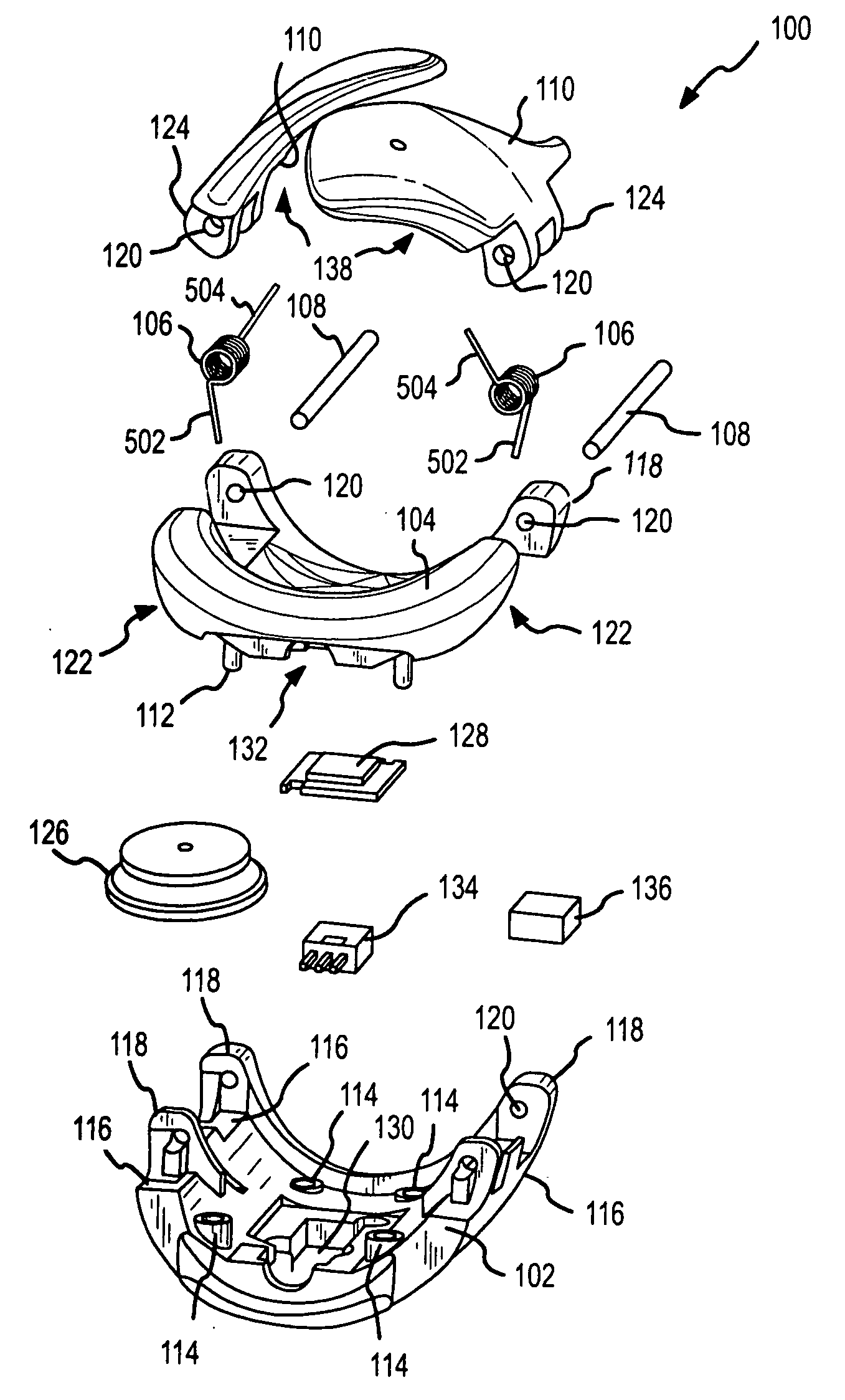
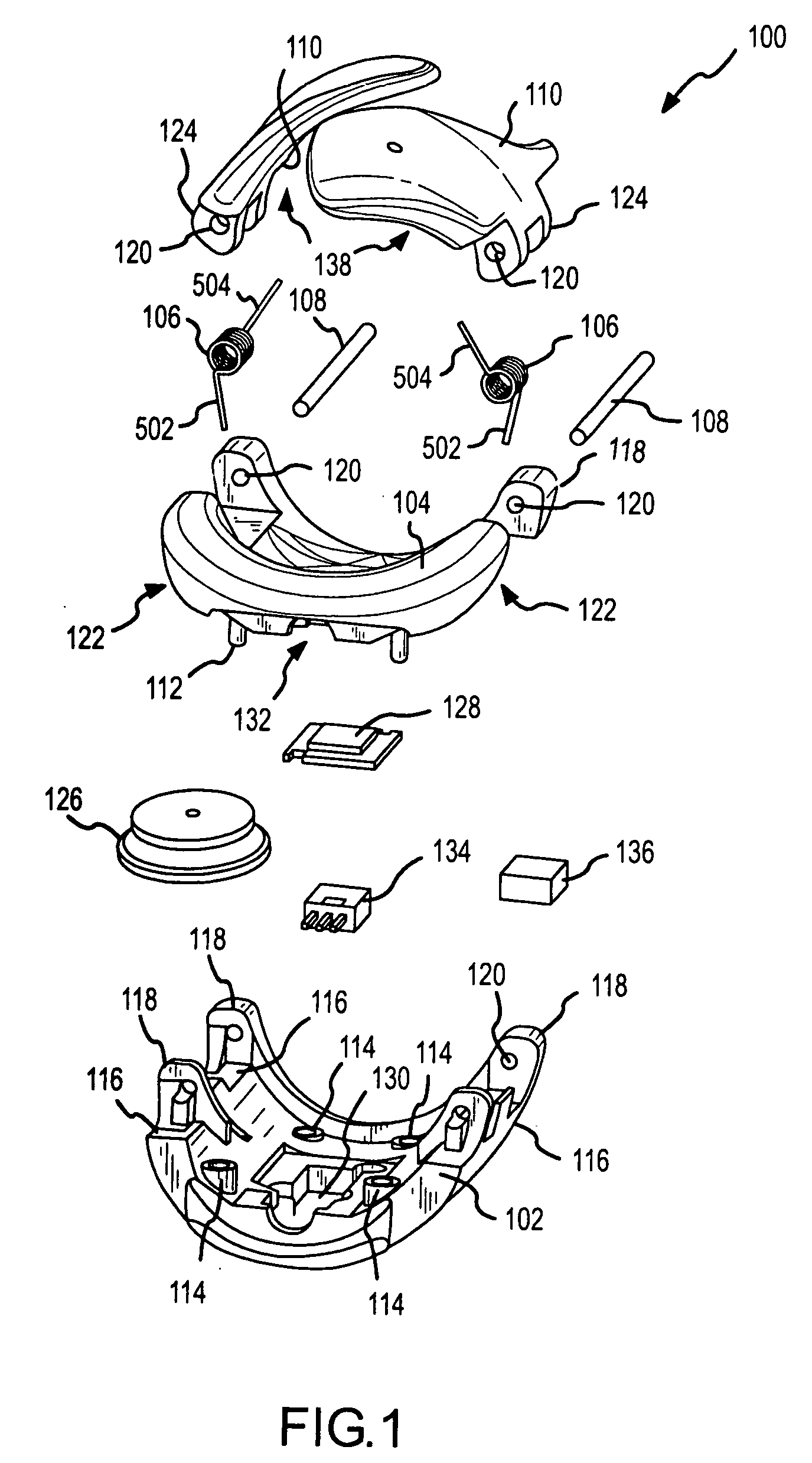
[0020] Referring first to FIG. 1, an exploded view of a biofeedback sensor 100 is shown. Biofeedback sensor 100 includes a bottom 102, a finger rest 104, a pair of elastic biasing members 106, such as the springs as shown, pins 108, and a pair of top wings 110 or panels. While shown with two elastic biasing members 106 and...


PUM


Abstract

The present invention provides a novel ring type sensor for measuring biometric information. The ring sensor includes a rest for an appendage and a wing pivotally connected to the rest. A biasing member supplies a compressive force to the wing (relative to the rest) such that an appendage from which biometric information is to be measured is snuggly held by the rest and the wing.

Description

FIELD OF THE INVENTION [0001] The present invention relates to biofeedback sensors and, more particularly, to biofeedback ring sensors. BACKGROUND OF THE INVENTION [0002] Biofeedback sensors provide information about physiological aspects of a person. In some biofeedback sessions, the client sits in a chair or lays on a couch or bed. Sensors are attached to the client's skin at various locations on the body, such as, for example, the shoulders, fingers, back, and head. Electrical signals or impulses from these locations are used to provide visual or auditory feedback reflecting various information. Other variations on biofeedback sessions are possible, with the above being an exemplary type of biofeedback session for background purposes. [0003] Some biofeedback sensors are simple electrodes attached to the client using an adhesive tab with an electrical contact or electrode. These adhesive tabs are placed in the desired locations on the client with the electrode between the client's...

Claims


Application Information

Patent Timeline
Patent Type & Authority Applications(United States)
IPC IPC(8): A61B5/00A61B5/02A61B5/024A61B5/05
CPCA61B5/02A61B5/02438A61B5/1455A61B5/6826A61B5/6838
Inventor SMITH, KURTBELL, CORWINDELANEY, JANGILBREATH, TODDALIPOUR, EHSANNUTT, TIMOTHYSCHULTZ, ERIC EDWARD
Owner HEALING RHYTHMS
Learn More